background image


Operation 

Page 14 


4.3 

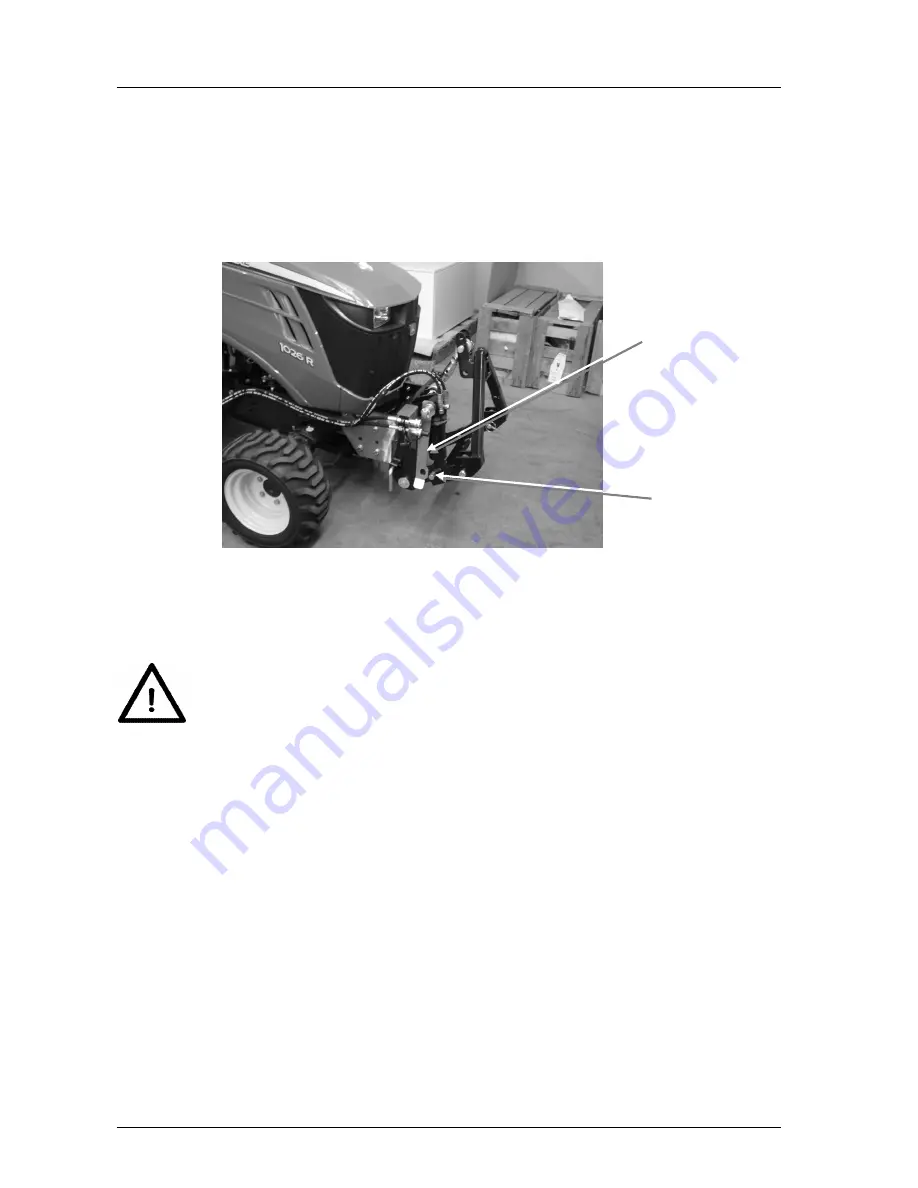
Lowering safeguard for the front power system 



Use the lowering safeguard for: 
– Driving on roads 
– Driving between work locations 
– Performing cleaning and maintenance tasks 


Fig. 11: Lowering safeguard, shown in unlocked position 

1. 

Lift the front power system. 

2. 

Pull off the linch pin on the bolt and fit the lowering safeguard on the bolt. Then se-
cure the connection with the linch pin again. 


Strictly avoid lowering the front power system via the tractor's control lever 
when the lowering safeguard is locked. 
Otherwise parts of the front power system could be damaged! 


Lowering safeguard 

Bolt with linch pin 

Summary of Contents for FPS-JD 1026 R

Page 1: ... 9101 9087 20 info matev eu www matev eu Version 06 2015 Original operating manual FPS JD 1026 R 131 8140 Front Power System 131 8141 Front PTO shaft 131 7454 Hydraulic Extension Kit 131 7456 Mower Attachment Kit 131 8142 Attachment Kit Orig John Deere Front PTO Shaft ...

Page 2: ...hydraulic extension kit 10 3 5 Mounting the rear mower attachment kit 11 3 6 Attachment kit for original John Deere front PTO shaft 12 3 6 1 Installation of the front PTO shaft front 12 3 6 2 Installation of the original John Deere universal joint shaft 12 4 Operation 12 4 1 Attachment variants for the coupling support 13 4 2 Coupling and uncoupling implements 13 4 3 Lowering safeguard for the fro...

Page 3: ...ssible for matev to assume liability for damage that is attributed to improper use or non intended use Keep this operating manual where it is easily accessible This will enable you to refer to important information and handling instructions as needed Listings with bullet points are marked as follows Text Text Text Handling instructions are marked in the sequence in which they should be executed as...

Page 4: ... For implements that contact the ground or roll on the ground in operation the tractor hydraulic system must be switched to the float setting Strictly comply with the manufacturer s rec ommendation The front power system is not suitable for lifting people or for use as a work platform In addition compliance with the service and maintenance guidelines is a component of intended use Moreover intende...

Page 5: ... the subsequent chapters In addition to the safety aspect you will save money and work time if you follow these safety instructions Danger Severe injury to the operator or third parties occurs Comply with the safety notice Attention Minor injury of the operator or third parties can occur The tractor the front power system or the environment can be damaged Comply with the safety notice Note Importa...

Page 6: ...th the notice in the operating manual Attention Danger of crushing due to moving parts Never reach into the crushing hazard danger zone if parts are moving or can move Comply with the notice in the operating manual Attention Increased risk of accident due to rotating PTO shaft Do not enter the work area of the PTO shaft when it is rotating For your own safety do not wear any loose clothing straps ...

Page 7: ... included in the scope of delivery Fig 1 Attachment bracket The actual front power system is only hooked into the provided aperture on the attach ment bracket with the cross member of the front power system and locked with the two angle bolts left right on the lugs The arrest nuts on the lugs can be omitted for faster dismounting e g frontloader However this can result in higher noise levels Conne...

Page 8: ...emble the drive shaft with the drive shaft holder and the protective pot Then pull out the arrest bar included in the scope of deliv ery of the attachment bracket and slide the pre assembled drive shaft holder into the at tachment bracket Fig 3 Front PTO shaft holder front Front PTO shaft holder front with drive shaft and without protec tive pot Angle bolts Lugs Arrest nuts ...

Page 9: ...ube holders The front protective tube holder is also fastened on the drive shaft The rear protective tube holder must be mounted on the underside of the tractor as shown in the following photo Fig 4 Protective tube holder front Fig 5 Protective tube holder rear Protective tube holder front Protective tube holder rear ...

Page 10: ...e the outer fork onto the profile stub of the mid mount PTO shaft of the tractor and release the locking pin locking ring 3 Slightly move the universal joint shaft back and forth until the locking pin audibly locks in place 4 Repeat steps 1 to 3 to attach the universal joint shaft on the front drive shaft tube 5 Fix the front protective tube on the front protective tube holder with screws and with...

Page 11: ... 5 Mounting the rear mower attachment kit The mower attachment kit is already integrated in the attachment bracket of the front power system To attach the mid mount mower the front power system must be unhooked Fig 8 Mower attachment kit Mower attachment kit ...

Page 12: ...lide the outer fork onto the profile stub of the mid mount PTO shaft of the tractor and release the locking pin locking ring 4 Slightly move the universal joint shaft back and forth until the locking pin audibly locks in place 4 Operation Before starting up the implement read the instructions on safety and han dling for operation of the entire implement and connection to the tractor In addition pr...

Page 13: ...ncreased by 45 mm with stronger take up Couple the triangle in points A and D 4 2 Coupling and uncoupling implements Comply with the axle loads specified by the tractor manufacturer 1 Drive the tractor forward in front of the implement 2 Lower the front power system hydraulically 3 Drive slowly toward the implement until the coupling triangle of the tractor is under the coupling triangle of the im...

Page 14: ...guard shown in unlocked position 1 Lift the front power system 2 Pull off the linch pin on the bolt and fit the lowering safeguard on the bolt Then se cure the connection with the linch pin again Strictly avoid lowering the front power system via the tractor s control lever when the lowering safeguard is locked Otherwise parts of the front power system could be damaged Lowering safeguard Bolt with...

Page 15: ...se the moving parts of the implement Grease the bearing on the PTO shaft drive Grease the lowering safeguard Grease the arrest bolt Check the seat status and seal of the hydraulic lines Before and after each use check all threaded unions for firm seat and re tighten them if necessary Repairs on parts that are under tension springs pressure accumulators require adequate skills and prescribed tools ...

Page 16: ...aults problems or other indications of malfunction contact your sales consultant or contact the manufacturer directly matev GmbH Nürnberger Str 50 90579 Langenzenn Tel switchboard 09 101 90 87 0 Enter the article number and the VIN number here This information is on the type plate of the device Article number Chassis number 7 Disposal The implements must be disposed of in accordance with the appli...

Page 17: ... acting cylinder Lift force Do not exceed the permissible axle loads of the vehi cle Front power system Removable quick coupling system Front PTO shaft Removable Weight 49 kg 9 2 Accessories Accessories Order number Front PTO shaft 131 8141 Hydraulic extension kit 131 7454 Front weight holder 131 5248 Mower attachment kit for John Deere mid mount mower 131 7456 Attachment kit original John Deere f...

Page 18: ...t holder front 8 Fig 4 Protective tube holder front 9 Fig 5 Protective tube holder rear 9 Fig 6 Hydraulic extension kit 10 Fig 7 Hydraulic extension set rear 11 Fig 8 Mower attachment kit 11 Fig 9 Drive shaft holder for JD front PTO shaft without mounted bearing shell 12 Fig 10 Coupling triangle 13 Fig 11 Lowering safeguard shown in unlocked position 14 ...

Page 19: ...ares that the machine FPS JD 1026R 131 8140 Front power system 131 8141 Front PTO shaft 131 7454 Hydraulic extension kit 131 7456 Mower attachment kit 131 8142 Attachment kit orig John Deere front PTO shaft complies with the provisions of the Machinery Directive 2006 42 EC and with the implementing national statutory regulations The signer is authorized to compile the technical documents The addre...

Reviews:

Related manuals for FPS-JD 1026 R