background image


24 

MUSTS5003_05 20211101


Emergency Shutoff 

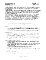
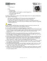
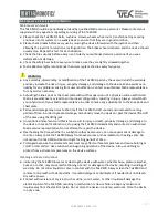
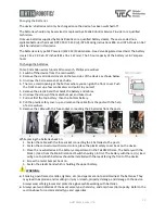
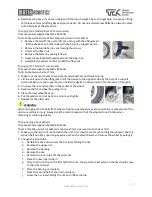
In emergency situations, the Tek RMD can be turned off at any time using the device’s Main 

Disconnect 

Switch. Once the switch is press

ed, the Tek RMD’s brakes will immediately 

engage, and all electric 

functions will cease. 
The Tek RMD is equipped with brakes that release when voltage is applied. During operation, the control 
unit first applies voltage to brakes to release them before applying energy to the drive motors to propel 
the Tek RMD. In the case of a power failure the brakes automatically return to the closed position 
bringing the device slowly to a halt. 
If any malfunctions occur, such as an excessive supply of energy to the system or a communications 
disruption, the sof

tware will disengage the Tek RMD and trigger the platform’s emergency brake 

system. After each emergency stop, the controls of the Tek RMD must be reactivated. If the driving 
function is still not available after switching the controls on, a caregiver must unlock the brakes to push 
the device. In this circumstance, contact a Matia Robotics dealer as soon as possible. 

NOTE

: If the 

batteries are fully discharged, the system

’s automatic motor brake system will activate. 


In such circumstances,  

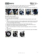
1.


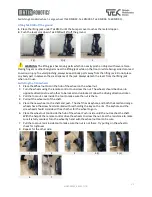
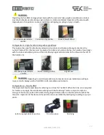
A caregiver must release the motor release arms on both sides. 

2.


Push the Tek RMD to a chair or a bed that the user wants to sit down on.  

3.


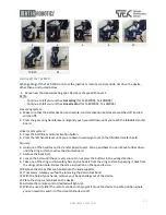
Locks the motor release arms and removes the spring belts and back belt. If the device has foldable 
transfer board the caregiver opens the board. 

ATTN:  

-


Continue to 

4

 if the unit has 

Gas spring 

(Tek RMD01, Tek RMD04, Tek RMD05, Tek RMD08)


-


Continue to 

6

 if the unit has 

Linear motor 

and the user is

 standing 

(Tek RMD02, Tek RMD03, Tek 

RMD06, Tek RMD07)


-


Continue to 

9

 if the unit has 

Linear motor,


Foldable transfer board

 and the user is

 sitting 

(Tek 

RMD02, Tek RMD06). 


Gas spring system: 

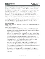
4.


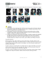
Make sure that the handle lever is locked into position. Hold the device firmly, while the right lever 
is engaged, push the Main Arm downward until the user is in a seated position. Release the right 
lever and remove the back belt after the user is seated.  

5.


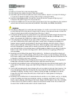
Once seated, unscrew the short end of the safety bar and pull it out.  Spin the remaining bar until 
the short side comes up to the center of the hole. Push the bar out from the hole. Repeat for the 
opposite side. 

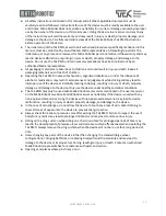
Linear motor system- The user is standing: 

6.


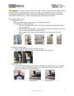
The caregiver makes sure the back belt is securely holding the user. Caregiver holds the user firmly 
in a standing position.  

7.


The user unscrews the short end of the safety bar and pulls out. Spins the remaining bar until the 
short side comes up to the center of the hole and pushes the bar out from the hole. The sling 
cushion falls to the side. 

8.


The caregiver removes the back belt and helps the user to safely sit down.  

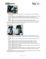
Linear motor system and foldable transfer board- The user is sitting: 

9.


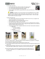
Unscrew the short end of the safety bar and remove.  Spin the remaining portion of the bar until 
the short side comes up to the center of the hole. Push the bar out from the hole. Repeat for the 
opposite side. 

10.


Moves his body back on the chair. 

11.


Once the user is sitting on the chair securely, he moves his legs out of the device with his hands. 

Summary of Contents for TEKRMD01

Page 1: ......

Page 2: ...PLIER This user manual MUST be given to the user of the device USER Please read this user s manual carefully before using your Tek RMD as it contains important information necessary for the safe and s...

Page 3: ...18 Switching Standard wheel Large wheel Tek RMD02 Tek RMD03 Tek RMD04 Tek RMD05 21 Lifting Tek RMD off the ground 21 Switching the front wheels 21 Changing the tail 22 Maximum safe driving angle indi...

Page 4: ...The first is a linear motor module which replaces the gas spring module and enables motorized standing sitting functions for users with limited strength in their upper body The second module consists...

Page 5: ...chnical Service Tek RMD technical service and repair must be performed by an authorized Matia representative as specified within the technical service manual Any attempts to service or repair the devi...

Page 6: ...ied in RESNA WC 1 2009 Sec 15 Explanation of Symbols Warning Symbols and Type Plates On the Tek RMD you will find the following symbols and labels attached 1 Warning Warning indicates a potentially ha...

Page 7: ...ls on all surfaces Orange zone Correct angle for driving with Standard wheels on flat surfaces Operating the device in standard Indoor wheel mode with a standing angle above the maximum safe driving a...

Page 8: ...tor units 4 Foldable transfer board 5 Dual Drive 1 User Panel 2 Chest Plate 3 Handle Lever Left1 4 Handle Lever Right1 5 Hip adjustment bars 6 Handles 7 Main Arm 8 Front Cover 9 Main Body 10 Knee Supp...

Page 9: ...moving 7 Left Right Belt Buttons Tightens and loosens the right left belt separately 8 Battery Indicator The battery indicator displays the amount of power left in the device s batteries 9 Remote Con...

Page 10: ...turns right 3 Go Back The device moves backward 4 Turn Left The device turns left 5 Horn The horn will sound when pushed To move the device in an angle simultaneously press the 2 directions you would...

Page 11: ...atory for proper device performance Using the Tek RMD without ensuring that all device parts and safety functions are in safe and proper working condition may lead to device malfunction misuse and tip...

Page 12: ...ront of you using either the Remote Control or User Panel 4 Remove the Sling Cushion from the device While in a seated position move slightly forward so that you can leave enough space to position the...

Page 13: ...andle lever and pull yourself up towards the handles release the right handle lever Repeat these two steps until you are in a fully upright position Once you are fully upright adjust your posture usin...

Page 14: ...ng the device for Tek RMD01 Tek RMD03 Tek RMD05 Tek RMD07 During the dismounting process do not use the joystick or remote control and do not drive the device other than as instructed below 1 Set the...

Page 15: ...device make sure the chest shield the hip adjustment bars or any other part of the unit is not pressing your body or legs or pressing your body to the seat Placing pressure to the body may cause pres...

Page 16: ...ivot upwards then it follows the carrier downward and becomes fully vertical stowing just behind your legs 18 Depress the left side lever to unlock the Handle Arms and push the Handle Arms fully upwar...

Page 17: ...n low enough to reach the foldable transfer board All units 6 Hold one of the handles on the transfer board covers Pull up and back to open Move further down until the sling cushion touches the transf...

Page 18: ...afest path of travel away from any potential obstructions Also avoid leaning and shifting weight and balance to one side of the device Remain in the normal seated or standing position Ask for assistan...

Page 19: ...he device along the best path of travel avoiding any transitions higher than 1 5 inches 40 mm When traversing obstacles the Tek RMD must be driven perpendicular over the obstacle without stopping Fail...

Page 20: ...sm Screw the 2 stoppers on the sides of the body The bended tips should be pointing toward the device Screw the first arm in the hole on the main body Screw the second arm on top of the first arm The...

Page 21: ...by placing the tool on the nut holding it still and turning the wheels by driving via remote control There is a label on the back side of the tool to show the direction to drive to lock and unlock th...

Page 22: ...nut 2 Turn the wheels using the remote control to unscrew the nut The wheels should be driven in opposite directions to each other to be locked and unlocked Follow the driving direction sticker 3 Pull...

Page 23: ...safe driving angle indicator Shows the correct driving angle of the user the furthest position that the main arm should be when driving with large wheels on varying surfaces Driving on a steeper angle...

Page 24: ...with the Indoor Outdoor portion of the Safe Driving Angle Indicator label on the shroud to the left of the handle arm Safe driving angle indicator position Correct standing position Large Wheel Opera...

Page 25: ...pens the board ATTN Continue to 4 if the unit has Gas spring Tek RMD01 Tek RMD04 Tek RMD05 Tek RMD08 Continue to 6 if the unit has Linear motor and the user is standing Tek RMD02 Tek RMD03 Tek RMD06 T...

Page 26: ...attempt to disengage the brakes while secured in the Tek RMD Attempting to reach the levers will cause instability and tipping resulting in injury or death property damage and damage to the device Ch...

Page 27: ...Robotics representative for any battery charger replacements Operating the Tek RMD or sitting and standing while simultaneously recharging the batteries can lead to damage to the device and malfuncti...

Page 28: ...ents to the knee pads and chest plate Permanent damage may occur to the tires if the Tek RMD is left unused and unmoved for a long period of time In order to prevent damage occasionally move the devic...

Page 29: ...cables 6 Unscrew the screws of the metal bumper and take it out 7 Pull out first the top battery then the bottom battery 8 Pull the plastic safety cover up and remove the cable from the post with the...

Page 30: ...n tilted position for the steps 3 through 8 3 Unscrew the nut and washers in the center of the wheel 4 Remove the front wheel by pulling it out 5 Place the new wheel back on 6 Put the washer and nut b...

Page 31: ...f valve 2 There are 6 pins inside of the wheel s rim Place an Allan wrench in the hole of the pin and unscrew it If the nut on the other side turns with the pin making it hard to unscrew place your fi...

Page 32: ...m a licensed healthcare practitioner is forbidden and will result in legal repercussions as well as voiding the warranty In the case of user sale the user assumes all liability related to the use of t...

Page 33: ...nd judgement while driving and may lead to improper use of the device or instability leading to tipping resulting in injury or death property damage and damage to the device Only use the device under...

Page 34: ...part of the linear motor assembly and the leg support s For all units Location 3 Between the front of the lower part of the main arm and the fixed shroud For all units Location 4 Between the lower pa...

Page 35: ...not disengaged Spare parts Matia Robotics supplies individual parts or modules to Distributors Your distributor can provide all spare parts for your Tek RMD Matia Robotics does not provide any replace...

Page 36: ...o them 3 If unintended movement or brake release occurs turn off TEK RMD as soon as it is safe 4 Be aware that adding accessories or components or modifying TEK RMD may make it more susceptible to int...

Page 37: ...tandard Ref Disclosure information RESNA Tek RMD All Models Standard Wheel Mode Large Wheel Mode Resna WC 1 Section 1 9 2 Static stability forward wheels unlocked 13 5 degrees 14 2 degrees Resna WC 1...

Page 38: ...5 inches 62 inches Resna WC 1 Section 5 8 13 Turning diameter 58 3 inches 62 inches Resna WC 1 Section 5 8 14 Ground clearance 1 8 inches 3 inches Resna WC 1 Section 5 8 15 Required width of angled c...

Page 39: ...ass 264 5 lbs Information Related to IEC 60601 1 2 Medical electrical equipment Part 1 2 General requirements for basic safety and essential performance Collateral Standard Electromagnetic disturbance...

Page 40: ...onment HOME HEALTHCARE ENVIRONMENT Conducted and radiated RF EMISSIONS CISPR 11 CISPR 11 Harmonic distortion See IEC 61000 3 2 See IEC 61000 3 2 Voltage fluctuations and flicker See IEC 61000 3 3 See...

Page 41: ...tition frequency Surges Line to line IEC 61000 4 5 0 5 kV 1 kV Surges Line to ground IEC 61000 4 5 0 5 kV 1 kV 2 kV Conducted disturbances induced by RF fields IEC 61000 4 6 3 V 0 15 MHz 80 MHz 6 V in...

Page 42: ...41 MUSTS5003_04 20210501...

Reviews: