27
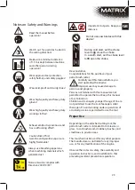
RISK OF INJURIES
CAUTION: Always wear protective
gloves when working with and
around cutting tools.
The cutting blade must be sharpened periodically
according to instructions. Improperly sharpened
or blunt cutting edges may cause the tool to
overload.
RISK OF RUPTURES and CRACKS
Fragments hurled away from the cutting tool can
cause extremely severe injuries.
To use the petrol cutting blade as an
engine powered trimmer, the proper guard
and cutting blade must be attached.
- Use a screwdriver, or the supplied Allen key to
fix the shaft of the petrol cutting blade
at the intended location by a locknut. Now
remove the line cassette (13) from the shaft by
turning it in clockwise direction (B11).
- Place the cutting blade (12) on the locking part.
- Place the retaining disk (observe side) and the
lock washer on the cutting blade (11) (B13).
- Use a screwdriver, or the supplied Allen key to
fix the shaft of the petrol cutting blade
at the intended location by a locknut. Screw the
hexagonal screw on the shaft in anti-clockwise
direction, and use the supplied hexagonal
wrench (15) to tighten this screw (B14).
CAUTION: Left-handed Thread
Assembly of Carrying Strap
The petrol cutting blade must be used with a
carrying strap (17).
First, balance the petrol brush cutter
when the tool is swithced off.
Assembly of Line Cassette
To avoid the risk of an unwanted engine start, pull
out the spark plug.
RISK OF INJURIES
CAUTION: Always wear protective
gloves when working with and around
cutting tools.
The petrol cutting blade is supplied with attached
cutting blade (11) and associated guard (12).
To use the petrol cutting blade as grass trimmer,
proper guard (12) and line spool (13) must be
attached.
- Use a screwdriver, or the supplied Allen key (14)
to fix the shaft of the petrol brush cutter at the
intended location (B6) by a locknut.
- Use the supplied hexagon wrench (15) to loosen
the hexagonal screw for attachment of the
cutting blade (B7) by turning it in clockwise
direction.
- Remove the hexagonal screw, the lock washer,
and the retaining disk for the cutting blade (B8).
Keep these parts at a safe location.
- Attach the locking part (B9).
- Use a screwdriver, or the supplied Allen key to
fix the shaft of the petrol cutting blade
at the intended location by a locknut (B10).
- Now screw the line cassette (13) onto the shaft
in a counter-clockwise direction (B10).
CAUTION: Left-handed Thread
Assembly of Cutting Blade
To avoid the risk of an unwanted engine start,
pull out the spark plug socket.
Summary of Contents for 310.750.230
Page 2: ...A2 A3 A4 A1 8 9 10 7 4 5 3 6 18 1 2 19 12 11 20...
Page 3: ...3 B1 B3 B2a B2b B2c 13 17 16 15 14 21...
Page 4: ...4 B4 B6 B8 B10 B12 B9 B11 B7...
Page 5: ...5 B16 B18 B17 B19 4 B15 OFF B20 B14 B13...
Page 6: ...6 B22 B24 B26 B23 B25 ON 18 6 5 B21 B27 B28...
Page 7: ...7 B33 B35 0 63 mm B31 B34 B36 B30 B29 B32...
Page 8: ...8 B37 B40 B39 B42 B41 B38...
Page 158: ...158 15 16 16 15 2000 14 EC 15 m 114...
Page 159: ...159 GR Raynaud...
Page 160: ...160...
Page 161: ...161 1 2 19 1 2 3 20...
Page 162: ...162 4 4 allen 14 4 2c 2 1 3 4 11 12 12 13 allen 14 6 15 7 8 9 allen 10 13 10...
Page 165: ...165 2 cm 2 cm...
Page 166: ...166 32 5 gr 33 34 0 25 0 63mm 35 36 37 27 28 29 10 30 31 25 allen...
Page 167: ...167 12 15 Nm 38...
Page 169: ...169 40 1...


