44
8.17 link ArM rePlAceMent
cHAPter 8: PArt rePlAceMent gUide
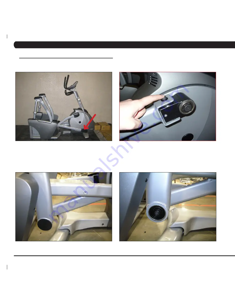
1) Remove the plastic cover at the joint of the link arm and the crank assembly (Figure A).
2) Disconnect the link arm from the crank assembly (Figure B).
3) Disconnect the pedal and link arm from the rear of the machine by separating the joint between the swing arm and the link arm. Remove the
plastic cap from the swing arm bushing to reveal the bolt and washer that hold the joint together. Remove the bolt (tighten to 28 N-m torque during
reassembly) (Figures C & D).
figUre A
figUre b
figUre d
figUre c
Summary of Contents for A5x-02
Page 1: ...A 5 x 0 2 A s c e n t T r a i n e r SER V ICE M A N U A l...
Page 2: ......
Page 5: ...1 SERIAL Number Placement Chapter 1 serial number location 1 1 SERIAL NUMBER LOCATION...
Page 20: ...16 7 1 Electrical Diagram Chapter 7 Troubleshooting...
Page 21: ...17 7 1 electrical diagram Chapter 7 Troubleshooting...
Page 22: ...18 System block diagram 7 1 electrical diagram Chapter 7 Troubleshooting...
Page 69: ...65 notes...


