31
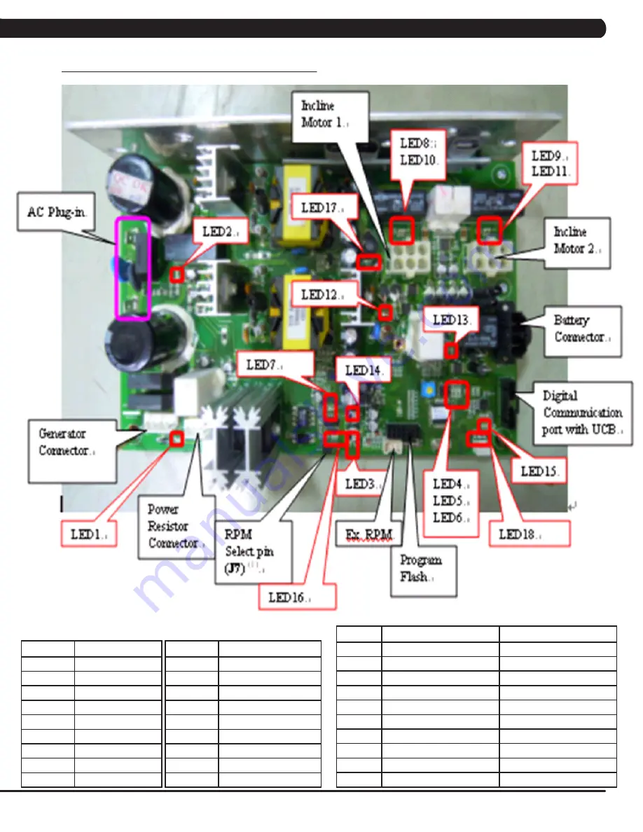
8.2 LCB ERROR INDICATORS
LED
DESCRIPTION
LED 1
Generator RPM
LED 2
AC Plug In
LED 3
Vcc (5V)
LED 4
System Status
LED 5
Error Status
LED 6
Error Status
LED 7
Resistance
LED 8
Incline 1 Forward
LED 9
Incline 2 Forward
LED
DESCRIPTION
LED 10
Incline 1 Rearward
LED 11
Incline 2 Rearward
LED 12
Charge
LED 13
Discharge
LED 14
12V / 6A (main power)
LED 15
Console Power
LED 16
E_RPM (external)
LED 17
15V / 8A (charge power)
LED 18
Cool Fan
CHAPTER 8: TROUBLESHOOTING
LED
PULSES / SECOND
DESCRIPTION
LED 4
2 times
Set for Self Powered System
1 time
Set for AC Plug In System
LED 5
2 times
Class B Error
1 time
Burn In
0.5 times
Class A Error
LED 6
2 times
Class C Error
0.5 times
Burn In
Bright
NO Resistance Offset.
LED 16
Bright
No Use
Pulse
Use
Summary of Contents for A7X-04
Page 4: ...1 SERIAL NUMBER LOCATION CHAPTER 1 SERIAL NUMBER LOCATION 1 1 SERIAL NUMBER LOCATION...
Page 31: ...28 8 1 ELECTRICAL DIAGRAMS CHAPTER 8 TROUBLESHOOTING...
Page 32: ...29 8 1 ELECTRICAL DIAGRAMS CONTINUED CHAPTER 8 TROUBLESHOOTING P21 Digital Communication Wire...
Page 33: ...30 8 1 ELECTRICAL DIAGRAMS CONTINUED CHAPTER 8 TROUBLESHOOTING P25 Hand Pulse Connecting Cable...
Page 92: ...89 NOTES...

