background image

3

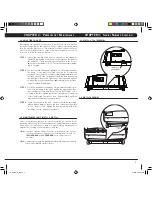
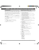
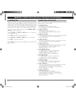
2.4 ADJUSTING THE BELT

After placing the treadmill in the position it will be used, the belt must be 
checked for proper tension and centering.  The belt might need to be adjusted 
after the first two hours of use.  Temperature, humidity, and use cause the 
belt to stretch at different rates.  If the belt starts to slip when a user is on 
it, be sure to follow the directions below.

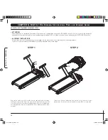
Locate  the  two  hex  head  bolts  on  the  rear  of  the  treadmill.  
The bolts are located at each end of the frame at the back of 
the treadmill.  These bolts adjust the rear belt roller.  Do not 
adjust until the treadmill is on.  This will prevent over tighten-
ing of one side.

The  belt  should  have  equal  distance  on  either  side  between 
the frame.  If the belt is touching one side, do not start the 
treadmill.  Turn the bolts counter clockwise approximately one 
full turn on each side.  Manually center the belt by pushing 
the belt from side to side.  Tighten the bolts the same amount 
as when the user loosened them, approximately one full turn.  
Inspect the belt for damage.

While the treadmill is running at 3 mph, observe the belt posi-
tion.  If it is moving to the right, tighten the right bolt by turn-
ing it clockwise ¼ turn, and loosen the left bolt ¼ turn.  If it is 
moving to the left, tighten the left bolt by turning it clockwise 
¼ turn and loosen the right ¼ turn.  Repeat Step 3 until the 
belt remains centered for several minutes.

Check the tension of the belt.  The belt should be very snug.  
When a person walks or runs on the belt, it should not hesitate 
or slip.  If this occurs, tighten the belt by turning both bolts 
clockwise ¼ turn.  Repeat if necessary.

2.5 MAINTENANCE LAMP (MX-T3

X

 & MX-T3xi)

There is a maintenance lamp on the console to remind the owner to do the 
scheduled maintenance. When the treadmill's accumulated distance reaches 
5000  miles,  the  maintenance  lamp  will  light  meaning  maintenance  is 
needed. The following is the maintenance lamp key:

• 

Blue

: It means that the treadmill needs to be maintained. To turn

               off the maintenance light after performing service, hold the
          

INCLINE DOWN

 and 

SPEED DOWN

 at the same time for 3 

            seconds.

• 

Red

: It means that the treadmill might have a problem, and needs to be checked.

           Please contact MATRIX customer service.

STEP 1

STEP 2

STEP 3

STEP 4

CHAPTER 2:  P

reventative

 m

aintenance

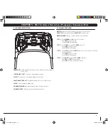
CHAPTER 3:  S

erial

 n

umber

 l

ocation

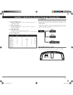
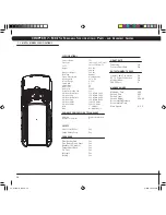
3.1 MX-T3x & T3xi TREADMILL

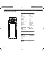
SERIAL #

PLACEMENT

SERIAL #

PLACEMENT

3.2 MX-T5x TREADMILL

06'_Treadmills_M.indd   7

7/18/06   4:00:03 PM

Summary of Contents for COMMERCIAL SERIES TREADMILL

Page 1: ...COMMERCIAL SERIES TREADMILL O W N E R S M A N U A L 06 _Treadmills_M indd 1 7 18 06 4 00 02 PM...

Page 2: ...06 _Treadmills_M indd 2 7 18 06 4 00 02 PM...

Page 3: ...eering Mode 4 7 MX T3x Manager Screen Descriptions Details 4 8 MX T3xi Manager Screen Descriptions Details 4 9 Using CSAFE CHAPTER 5 MX T5x OVERLAY DESCRIPTION ENGINEERING MODE 5 1 T5x Console Descrip...

Page 4: ...06 _Treadmills_M indd 4 7 18 06 4 00 02 PM...

Page 5: ...should always be followed including the following DANGER To reduce the risk of electric shock Always unplug this equipment from the electrical outlet immediately after using and before cleaning warnin...

Page 6: ...cleaning solutions on any surface This could cause electrocution 4 Wipe the console and side rails after every use 5 Brush away any wax deposits from the deck and belt area This is a com mon occurrenc...

Page 7: ...g to the right tighten the right bolt by turn ing it clockwise turn and loosen the left bolt turn If it is moving to the left tighten the left bolt by turning it clockwise turn and loosen the right tu...

Page 8: ...The MATRIX treadmill is inspected before it is packaged It is shipped in four pieces the base the upright console supports the handlebar and the console Carefully unpack the unit and dispose of the b...

Page 9: ...the LEVEL using SPEED then press SELECT 3 Choose the TIME using SPEED then press SELECT 4 Choose WEIGHT using SPEED then press SELECT 5 Press START 5K Run 1 Choose the 5K program using the program QUI...

Page 10: ...T TEST allows you to measure your fitness based on a program designed specifically for your Matrix Treadmill The test takes 5 minutes and is based on your heart rate User should keep hands on contact...

Page 11: ...e speed learn mode edit This variable controls the middle limit for the speed of the treadmill HIGH speed learn mode edit This variable controls the high limit for the speed of the treadmill low eleva...

Page 12: ...each engineering screens low speed learn mode edit This variable controls the low limit for the speed of the treadmill HIGH speed learn mode edit This variable controls the hight limit for the speed...

Page 13: ...Wait 5 seconds Select START will start program Select WEIGHT by using the UP or DOWN arrow keys Press START or Select to begin workout Display tIME Starting 3 Starting 2 Starting 1 Step 1 Step 2 Step...

Page 14: ...will be used to control the users heart rate Press start heart rate safety protocols polar target heart rate zone chart is on pg 11 When the users heart rate exceeds the target heart rate by the value...

Page 15: ...y TIME Starting 3 Starting 2 Starting 1 STEP 6 Display will read HOLD THE HANDGRIP SENSORS FORDETECTINGHR ifnoheartrateisfoundafter4 20 Displaywill read HR TO LOW RETRY THE TEST if score is over 80 ST...

Page 16: ...lay only Holding the start key resets the accumulated distance p7 Software version Active variable displayed in the time seven segment display Accumulated distance is not editable for display only p8...

Page 17: ...Channel Default Volume Speed Mode Out of Order minimum default 5 5 1 80 15 0 5 2 T4 OFF 1 1 maximum 95 NV max time 20 400 100 2 12 T5 ON 30 30 step size 5 5 1 5 1 0 1 0 1 1 1 1 1 units minutes minutes...

Page 18: ...5 Speed Max 12 Motor Type 3 2 HP DC Controller Cooling Fan Yes Electrical Receptacle 120 NEMA 5 20R Electrical Plug 120 NEMA 5 20P Electrical Receptacle 220 NEMA 6 20R Electrical Plug 220 NEMA 6 20R E...

Page 19: ...ired fasteners Assembley Tools 08 Z51 SOCKET HEAD CAP SCREW M10 x 25 01 8mm ALLEN WRENCH 01 10mm ALLEN WRENCH 02 Z52 BUTTON HEAD MACHINE SCREW M5 x 12L 08 Z50 FLAT WASHER 30x2 0L QTY PART SKETCH DESCR...

Page 20: ...Do not stand on the belt when performing the auto check function ASSEMBLY INSTRUCTIONS Please make sure that the power plug is not plugged into the wall outlet while completing the following procedur...

Page 21: ...INEERING MODE is shown onto the console Press the incline UP button to find the AUTO CHECK screen Press the incline START button and then the treadmill will run the auto check function automatically T...

Page 22: ...60 Incline Range 0 15 Speed Min 0 5 Speed Max 12 Motor Type AC Motor Size 5hp AC Controller Cooling Fan Yes Electrical Receptacle 110 NEMA 5 20R Electrical Plug 110 NEMA 5 20P Electrical Receptacle 2...

Page 23: ...T HEAD MACHINE SCREW M8 x 25L 01 5mm ALLEN WRENCH 01 ALLEN WRENCH 8 x 168 04 C24 BUTTON HEAD MACHINE SCREW M5 x 10L 02 Q28 END CAP 12 7 08 C10 FLAT HEAD MACHINE SCREW M8 x 20L QTY PART SKETCH DESCRIPT...

Page 24: ...ICK START CLEAR 1 2 3 4 5 6 7 8 9 0 TIME ELEV ATIO N DIST ANC E SPEE D PAUSE SELECT HOLD TO RESET KEYPAD MANUAL ROLLING INTERVA LS RANDO M FIT TEST TARGET HR QUICK START CLEAR 1 2 3 4 5 6 7 8 9 0 TIME...

Page 25: ...AR 1 2 3 4 5 6 7 8 9 0 TIME ELEV ATIO N DIST ANC E SPEE D PAUSE SELECT HOLD TO RESET KEYPAD MANUAL ROLLING INTERVA LS RANDO M FIT TEST TARGET HR QUICK START CLEAR 1 2 3 4 5 6 7 8 9 0 TIME ELEV ATIO N...

Page 26: ...06 _Treadmills_M indd 26 7 18 06 4 00 10 PM...

Page 27: ...MATrix Fitness systems corp 1610 Landmark Drive Cottage Grove wi 53527 USA TOLL FREE 866 693 4863 www matrixfitness com FAX 608 839 8687 REV 02 06 _Treadmills_M indd 27 7 18 06 4 00 11 PM...

Reviews: