21
cHaptEr 8: part rEplacEMEnt gUidE
8.1 front diSk rEMoVal
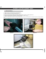
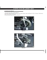
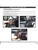
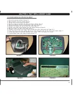
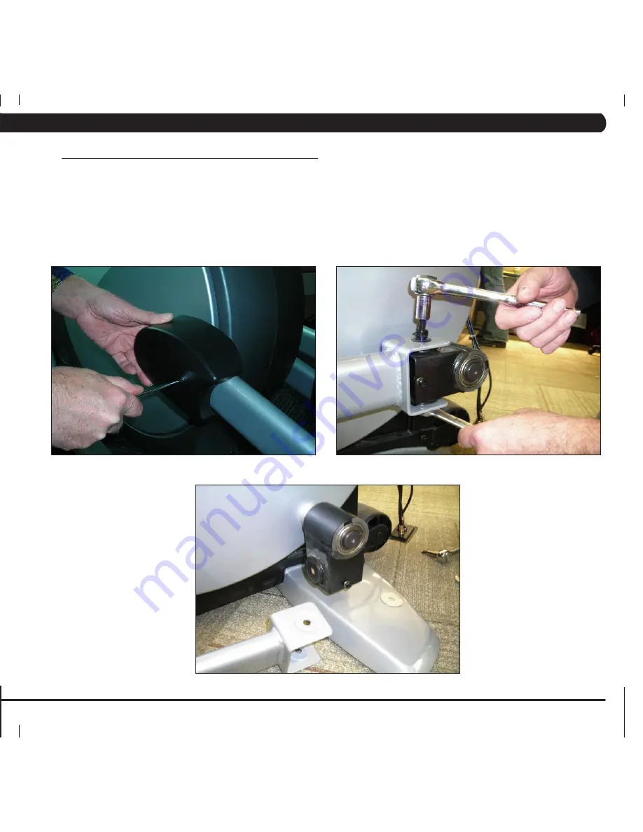
1) Remove the crank arm plastic cap at the front disk (Figure A).
2) Detach the crank from the crank arm (Figures B & C).
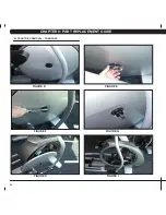
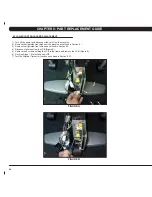
3) Locate the center cap in the center of the front disk (Figure D).
4) Turn the center cap counter clockwise with the palm of your hand and remove the cap and spring (Figure E).
5) Remove the 24mm locking nut and washer by turning them counter clockwise (Figure F).
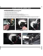
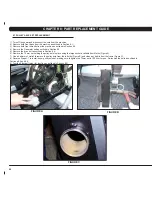
7) Thread the Matrix disk removal tool into the center hub (Figure G).
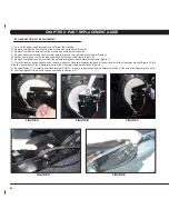
8) Turn the center bolt of the removal tool clockwise until the main disk can be removed (Figures H and I). Repeat if necessary for the opposite side
disk.
9) When reinstalling the 24mm nut, it should be tightened to 196 N-m Torque.
figUrE a
figUrE b
figUrE c
Summary of Contents for E3X-01
Page 1: ...E 3 x 0 1 e l l i p t i c a l T r a i n e r S E R V IC E M AN U A l...
Page 2: ......
Page 5: ...1 Chapter 1 Serial number location 1 1 SERIAL NUMBER LOCATION...
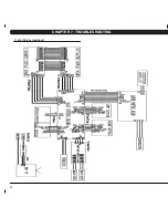
Page 16: ...12 Chapter 7 TROUBLESHOOTING 7 1 Electrical Diagrams...
Page 17: ...13 Chapter 7 TROUBLESHOOTING 7 1 electrical diagrams...
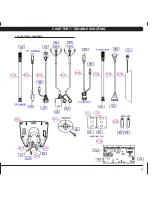
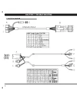
Page 18: ...14 7 1 electrical diagrams chapter 7 troubleshooting...
Page 65: ...61 notes...

