background image

2

2.1 rEad and SaVE tHESE inStrUctionS

This  Elliptical  Trainer  is  intended  for  commercial  use.  To  ensure 

your  safety  and  protect  the  equipment,  read  all  instructions  before 

operating the MATRIX Elliptical Trainer.

Remind the users that before undertaking any fitness program, they 

should obtain complete physical examinations from their physicians.  

If, at any time while exercising, the user experiences dizziness, 

pain, or shortness of breath, nausea or feels faint, he or she must 

stop immediately.  

•   This product must be used for its intended purpose 

described in this service manual.


Do not use other 

attachments that are not recommend by the manufacturer. 

Attachments may cause injury.

•   To prevent electrical shock, never drop or insert any object 

into any opening.  

•   Do not remove the console covers. Service should only be 

done by an authorized service technician.

•   Close supervision is necessary when the Elliptical Trainer 

is used by or near children or disable persons.

•  Do not use outdoors.  

•   Do not operate where aerosol (spray) products are being 

used or when oxygen is being administered.

•    Do not use the equipment in any way other than designed or 

intended by the manufacturer. It is imperative that all Matrix 

Fitness Systems equipment is used properly to avoid injury.

•  Keep hands and feet clear of moving parts at all times to  

  avoid injury.

•  Unsupervised children must be kept away from this equip 

  ment.

•  Do not wear loose clothing while on the equipment.

caUtion! 

 If you experience chest pains, nausea, dizziness, or 

shortness of breath, stop exercising immediately and consult 

your physician before continuing.  

caUtion! 

 Any changes or modifications to this equipment 

could void the product warranty.  

cHaptEr 2: iMportant SafEty inStrUctionS 

The Matrix E3x-01 Elliptical Trainer is designed to be self powered 

and does not require an external power supply source to operate. 

The battery in the console needs to be charged for 3-4 hours when 

first installed. Until the battery is fully charged, the 30 second pause 

feature  may  not  function  fully.  The  charging  does  not  need  to  be 

continuous for 3-4 hours, but over combined workouts equaling 3-4 

hours.   

2.2 ElEctrical rEqUirEMEntS

Summary of Contents for E3X-01

Page 1: ...E 3 x 0 1 e l l i p t i c a l T r a i n e r S E R V IC E M AN U A l...

Page 2: ......

Page 3: ...eps Constant Watts 8 CHAPTER 5 Manager MODE 5 1 Manager Mode Overview 9 5 2 Manager Mode Information 10 CHAPTER 6 engineering Service mode 6 1 Engineering Service Mode Overview 11 CHAPTER 7 TROUBLESHO...

Page 4: ...ebar Replacement 36 8 15 Console Mast Replacement 37 8 16 Foot Pedals Replacement 38 8 17 Pedal Arm Replacement 39 8 18 Crank Arm Replacement 41 8 19 Roller Replacement 43 8 20 Roller Track Replacemen...

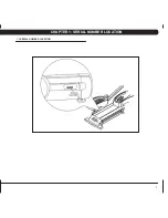
Page 5: ...1 Chapter 1 Serial number location 1 1 SERIAL NUMBER LOCATION...

Page 6: ...rs Do not operate where aerosol spray products are being used or when oxygen is being administered Do not use the equipment in any way other than designed or intended by the manufacturer It is imperat...

Page 7: ...ocks Maintain a clean area around equipment free from dust and dirt DO NOT use any equipment that is damaged or has worn or broken parts Use only replacement parts supplied by Matrix Fitness Systems m...

Page 8: ...echnical Support Team identifies items that require specific attention the latest version will always be available on the Matrix web site www matrixfitness com DAILY MAINTENANCE ITEMS 1 Look and liste...

Page 9: ...iner features eight programs START QUICK START One touch Quick Start and Start any time during preference selection UP DOWN LEVEL Easy information and level selection SELECT SELECT SCREEN RESET This m...

Page 10: ...ining program is a level based program that automatically adjusts the resistance of the machine from low to high intensity settings at regular intervals 1 Start pedaling and press the INTERVAL TRAININ...

Page 11: ...ompleted 1 Start pedaling and press the FITNESS TEST key 2 Select Age by using the UP or DOWN LEVEL keys and press SELECT 3 Select Gender by using the UP or DOWN LEVEL keys and press SELECT 4 Select W...

Page 12: ...te 1 Start pedaling and press the HEART RATE key 2 Select Age by using the UP or DOWN LEVEL keys and press SELECT 3 Select Target HR Percentage by using the UP or DOWN LEVEL keys and press SELECT 4 Se...

Page 13: ...isplay reads Manager Mode and hit SELECT Figure A 2 To scroll through the list of options in Manager Mode use the UP and DOWN LEVEL keys Each of the custom settings will show on the display 3 To selec...

Page 14: ...36 kg 400 lbs 181 kg Weight used for program calorie expenditure calculations Speed Distance Mode Mile Mile Kilometer Displays distance in miles or kilometers Machine Bike BI Elliptical EL Bike BI Thi...

Page 15: ...or 3 seconds until Manager Mode appears on the middle LED display Press the UP or DOWN LEVEL key to scroll between the different Engineering and Service Modes ENGINEERING MODE This mode is for factory...

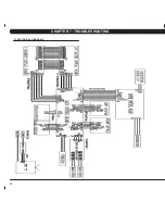
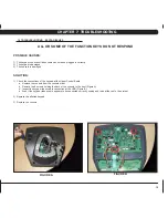
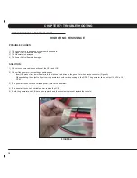
Page 16: ...12 Chapter 7 TROUBLESHOOTING 7 1 Electrical Diagrams...

Page 17: ...13 Chapter 7 TROUBLESHOOTING 7 1 electrical diagrams...

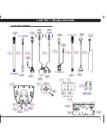
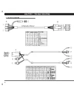
Page 18: ...14 7 1 electrical diagrams chapter 7 troubleshooting...

Page 19: ...pper Control Board a Remove the console from the console mast b Remove the 6 screws holding the back of the console to the front Figure A c Inspect the keypad ribbon cable connection at the UCB Figure...

Page 20: ...es from a multi meter into the black and red wires on the generator wire harness connector Figure A b When pedaling the output voltage from the generator should vary depending on the RPM The generator...

Page 21: ...r creaking noise Possible causes 1 The pedal is on the pedal arm too loosely 2 The drive axle is worn out 3 The belt tension is not enough or the belts are too dirty SOLUTION 1 Retighten the pedal ont...

Page 22: ...ent in Step 1 check the console cable connection at the lower control board Also check for any pinches or cuts in the console cable 3 Check if the generator is outputting variable power a Insert the p...

Page 23: ...is damaged 3 The lower control board is damaged SOLUTION 1 Remove the console and check to see if the console cable is connected properly 2 Check to see if the console cable is pinched or cut replace...

Page 24: ...strap is damaged 4 The HR grips are damaged 5 The HR board is damaged 6 The UCB is damaged SOLUTION 1 Re center the chest strap below the user s pectoral muscle Figure A and check again 2 Replace the...

Page 25: ...ise with the palm of your hand and remove the cap and spring Figure E 5 Remove the 24mm locking nut and washer by turning them counter clockwise Figure F 7 Thread the Matrix disk removal tool into the...

Page 26: ...22 Chapter 8 Part Replacement Guide 8 1 FRONT DISK REMOVAL CONTINUED figure f figure g figure h figure i figure d figure e...

Page 27: ...2 Remove the screws that hold the front shrouds in place and to each other on each side Figure A NOTE You will need to lift the console mast boot to remove some of the screws 3 Remove the front shrou...

Page 28: ...de front shroud as outlined in Section 8 2 4 Disconnect all wires from the LCB Figure A 5 Remove the 2 screws holding the LCB to the frame and remove the LCB Figure B 6 Reverse Steps 1 5 to install a...

Page 29: ...ut on the tension eye bolt on both sides of the frame Figure C 7 Remove the tension eye bolt nut from the Generator bracket on both sides of the frame Figure D 8 Once the tension eye bolts have been r...

Page 30: ...B 6 Remove the tension eye bolt nut from the Generator bracket on both sides of the frame Figure C 7 Once the tension eye bolts have been removed slide the Generator towards the back of the unit and o...

Page 31: ...counter clockwise until there is enough slack in the belt to remove it Figures A B 4 Walk the new drive belt into position on the drive assembly 5 Once the drive belt is in place reapply tension by ro...

Page 32: ...ion 8 6 6 Remove the 75 mm nut holding the pulley axle in place using the large socket available from Matrix Figure A 7 Use a hammer or mallet to remove the pulley axle from the left side Figure B and...

Page 33: ...washer around the 75 mm nut holding the drive axle set to the frame Figure A 7 Remove the 75 mm nut holding the drive axle set to the frame using the large socket available from Matrix Figure B 8 Rem...

Page 34: ...ve the console Figure B 3 Reconnect the wire connections to the new console 4 Carefully push the wires into the console and mast until they are clear of the console mast connection and attach the cons...

Page 35: ...hole in the console and plug it in Figure F 8 Match the overlay to the cutout on the console Figure G 9 Press down on the corners of the overlay to keep it in place then remove the protective film Fig...

Page 36: ...32 8 10 CONSOLE KEYPAD OVERLAY REPLACEMENT CONTINUED Chapter 8 Part Replacement Guide figure e figure f figure g figure h figure i figure j...

Page 37: ...inside the console mast until the connectors on the ends come free and disconnect 4 To install a new handlebar assembly connect the new handlebar and carefully push the heart rate wires into the conso...

Page 38: ...er Figure A 2 Pull the 2 halves of the HR grip apart Figure B 3 Disconnect the black wire and remove the lower portion of the HR grip Figure C 4 Disconnect the red wire and level button and remove the...

Page 39: ...crews holding the cup holder onto the console mast Figure A 2 Remove the cup holder Figure B 3 Reverse Steps 1 2 to install a new cup holder 8 13 CUP HOLDER REPLACEMENT Chapter 8 Part Replacement Guid...

Page 40: ...re B 3 Remove the two bolts holding the dual action handlebar to the console mast pivot Figure C 4 Remove the pivot cap and handlebar Figure D 5 Reverse steps 1 4 to install a new dual action handleba...

Page 41: ...e 4 screws holding the console mast onto the frame Figure D 5 Remove the console mast being careful to pull the console wires out of the bottom of the mast without damaging them 6 Reverse Steps 1 5 to...

Page 42: ...A 2 Remove the 4 Phillips screws that hold the plastic foot pedal to the foot plate Figure B 3 Remove the plastic foot pedal Figure C 4 Reverse Steps 1 3 to install a new foot pedal 5 Test the Ellipti...

Page 43: ...pedal as outlined in Section 8 16 4 Remove the 3 bolts that hold on the mounting plate at the crank arm pedal arm joint Figure D Note the plastic washer that mounts at the end of the shaft Figure E 5...

Page 44: ...40 figure d chapter 8 part replacement guide figure E figure F figure G 8 17 pedal arm replacement continued...

Page 45: ...n the pedal arm shaft Figure F 5 Remove the 2 screws on each side holding on the rear end cap and remove it Figure G H 6 Remove the middle plastic cover from between the pedals by pulling it towards t...

Page 46: ...42 Chapter 8 Part Replacement Guide 8 18 crank arm replacement continued figure e figure f figure g figure h figure i figure j...

Page 47: ...n the rear end cap and remove it Figure E F 4 Remove the middle plastic cover from between the pedals by pulling it towards the rear of the unit Figure G 5 Remove the 3 screws holding the top roller t...

Page 48: ...44 8 19 ROLLER REPLACEMENT CONTINUED Chapter 8 Part Replacement Guide figure e figure f figure g figure h figure i figure j...

Page 49: ...he rear end cap and remove it Figure E F 4 Remove the middle plastic cover from between the pedals by pulling it towards the rear of the unit Figure G 5 Remove the 3 screws holding the top roller trac...

Page 50: ...46 Chapter 8 Part Replacement Guide figure e figure f figure g figure h figure i figure j 8 20 roller track replacement continued...

Page 51: ...t for EL change to EL using the UP or DOWN LEVEL key and press START to save f Press the START key twice to return to normal function 1 Without hitting start or entering any exercise modes stand on th...

Page 52: ...istance Levels 25 Multi language Display Yes Coaxial Cable Connection Yes AC TV Power Connection Yes Monitor Mount Yes Technical data Power Requirements0 Self Powered Overall Dimensions L x W x H 75 x...

Page 53: ...ew M5x10L Red 04 Z04 See sketch of Z01 Socket HEad Cap Screw 65mm Green 02 Z05 See sketch of Z01 Socket Head Cap Screw M8x55L Yellow 02 Z06 Washer 8 2x16x1 0T Yellow 02 Z07 Nylon Nut M8x12 5P Yellow 0...

Page 54: ...ELLIPTICAL TRAINER ASSEMBLY STEPS Chapter 9 elliptical trainer specifications and assembly guide after these assembly steps are complete be sure to setup and test the unit as outlined in section 8 21...

Page 55: ...51 chapter 9 elliptical trainer specifications and assembly guide 9 3 elliptical trainer assembly steps continued Step 2...

Page 56: ...52 chapter 9 elliptical trainer specifications and assembly guide 9 3 elliptical trainer assembly steps continued Step 3...

Page 57: ...53 Chapter 9 elliptical trainer specifications and assembly guide 9 3 elliptical trainer assembly steps continued Step 4...

Page 58: ...54 Chapter 9 elliptical trainer specifications and assembly guide 9 3 elliptical trainer assembly steps continued Step 5...

Page 59: ...55 Chapter 9 elliptical trainer specifications and assembly guide 9 3 elliptical trainer assembly steps continued Final Assembly...

Page 60: ...cates that your Elliptical Trainer needs to be leveled Determine which leveler is not resting completely on the floor Loosen the nut with one hand to allow the leveler to rotate Rotate the left or rig...

Page 61: ...e in the rabbit ear to limit the angle of adjustment of the TV Figure G 8 Attach the TV to the rabbit ears using 4 screws from the hardware bag Figure H 9 Attach the TV controller bracket to the front...

Page 62: ...58 Figure C Figure D Figure E Figure F Figure G Figure H 9 5 TV Bracket installation continued Chapter 9 elliptical trainer specifications and assembly guide...

Page 63: ...59 Figure I Figure J Figure K Figure L Figure M Figure N 9 5 TV Bracket installation continued Chapter 9 elliptical trainer specifications and assembly guide...

Page 64: ...60 Figure O Figure P Figure Q Figure R 9 5 TV Bracket installation Continued Chapter 9 elliptical trainer specifications and assembly guide...

Page 65: ...61 notes...

Page 66: ...62 MATrix Fitness systems corp 1610 Landmark Drive Cottage Grove wi 53527 USA TOLL FREE 866 693 4863 www matrixfitness com FAX 608 839 1717 REV 02 KO...

Reviews: