53
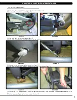
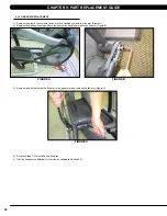
9.15 pEdal aRM REplacEMEnt
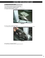
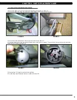
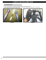
1) Remove the plastic cover where the pedal arm attaches to the crank (Figure A).
2) Disconnect the pedal arm from the crank (Figure B).
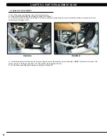
3) Remove the plastic cap from the swing arm (Figure C).
4) Remove the bolt that holds the pedal and swing arms together (Figure D).
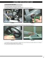
5) The swing arm can now be separate from the pedal arm (Figure E).
6) Remove the bolt that holds the link arm to the pedal arm and remove the pedal arm (Figure F).
7) Reverse Steps 1-5 to install a new pedal arm.
note:
Torque the bolt removed in Step 4 to 80 N-m and the bolt / nut removed in Step 2 to 70
N-m.
8) Test the Suspension Elliptical for function as outlined in Section 9.21
figuRE a
figuRE b
figuRE c
figuRE d
figuRE E
figuRE f
cHaptER 9: paRt REplacEMEnt guidE
Summary of Contents for E5X-04
Page 4: ...1 1 1 SERIAL NUMBER LOCATION SERIAL Number LOCATION CHAPTER 1 Serial Number Location...
Page 18: ...15 8 1 Electrical DiagramS CHAPTER 8 Troubleshooting HURES5x C Electrical block diagram...
Page 19: ...16 8 1 electrical diagramS CONTINUED Pulse Sensor Wire Chapter 8 Troubleshooting...
Page 21: ...18 POWER RESISTANCE WIRE ECB Wire 8 1 electrical diagramS Continued CHAPTER 8 Troubleshooting...
Page 24: ...21 8 4 LCB1_ErP wiring connection CHAPTER 8 Troubleshooting...
Page 84: ...81 notes...

