27
CHAPTER 5
:
PARTS REPLACEMENT
5.11 CONNECTION ROD
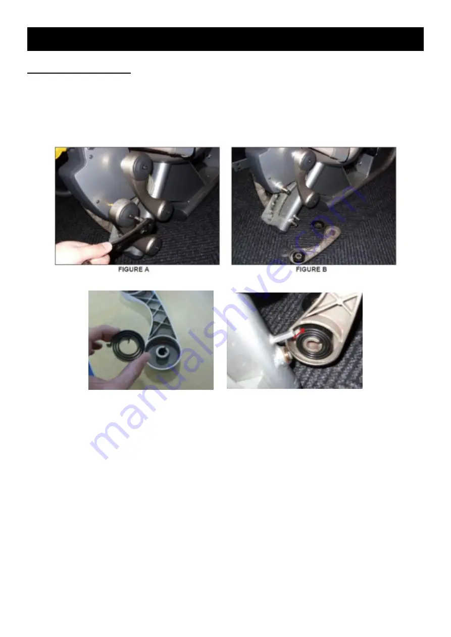
1) Remove the 2 screws going into the connecting rod (Figure A).
2) Remove the connecting rod (Figure B). (1000398860)
3) When installing a new connecting rod, make sure that the swirl spring is present and properly
installed (there should be at least 2 swirl springs for each set of 4 connecting rods) (Figures C & D).
FIGURE C
FIGURE D
Summary of Contents for G7-S34-02
Page 3: ...3 CHAPTER 1 SERIAL NUMBER LOCATION...
Page 6: ...6 CHAPTER 3 ASSEMBLY INSTRUCTION...
Page 7: ...7 CHAPTER 3 ASSEMBLY INSTRUCTION...
Page 8: ...8 CHAPTER 3 ASSEMBLY INSTRUCTION...
Page 10: ...10 CHAPTER 4 TROUBLESHOOTING 4 1 THE REPETITION IS BLANK OR IS NOT COUNTING MOVEMENTS...
Page 21: ...21 CHAPTER 5 PARTS REPLACEMENT 5 6 INCREMENTAL WEIGHT PIN...
Page 23: ...23 CHAPTER 5 PARTS REPLACEMENT 5 7 WEIGHT PLATE FIGURE I FIGURE J FIGURE H...


