13
CHAPTER 6: P
reventative
m
aintenance
b. Check brake pad setting by first turning the resistance knob toward the
“-“ sign as far as it will go (minimum braking effect). The brake pad should
have approximately a credit card thickness between it and the flywheel and
the brake pad should feel slightly loose around its pivot. If adjustment is
required see
TROUBLESHOOTING GUIDE
(see page 13).
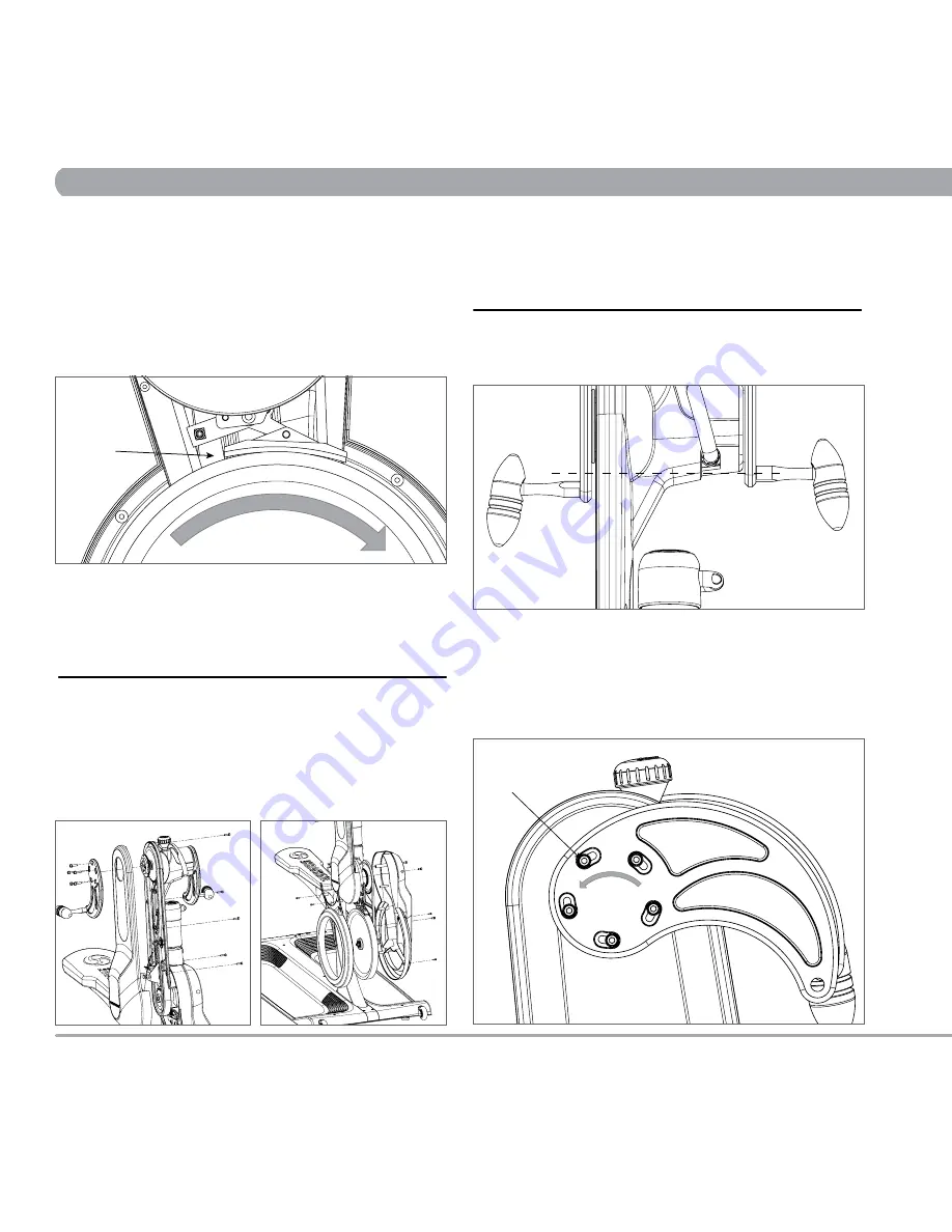
c. Check brake pad for signs of wear and the presence of lubrication. If the
brake pad requires lubrication, first adjust the resistance knob so the brake
pad is just slightly touching the flywheel. Then slowly rotate the flywheel
with one hand while applying a small amount of lubricant on the flywheel
just behind the brake pad (A) on the in-going side. Wipe off excess.
d. Replace brake pad if necessary
e. Replace lower inside plastic cover
2. Check and tighten (if necessary) the screws on crank arms, adjustment
knobs and levers, seat, water bottle holder, and plastic covers.
6.4 BI-YEARLY (6 MONTH) MAINTENANCE
1. For optimal performance of the drive system the following steps should
be taken:
a. Remove the RIGHT crank arm by removing 5 socket head cap screws
with a 4mm ALLEN KEY WRENCH then remove the upper outside plastic
cover by removing 5 socket head cap screws with a 3mm ALLEN KEY
WRENCH. Then remove both of the lower plastic covers by removing 9
socket head cap screws with a 3mm ALLEN KEY WRENCH and 5mm
ALLEN KEY WRENCH.
b. Thoroughly wipe down around all internal components and look for signs
of excessive wear or damage.
c. Lubricate both upper and lower drive chains. Clean excess.
d. Replace drive chains if necessary
e. Replace all plastic covers and RIGHT crank arm
6.5 TROUBLESHOOTING GUIDE
Follow the steps below if any problems are discovered in the weekly
function test.
CRANK ARMS NOT SYNCHRONIZED
Turn the resistance knob toward the “+” sign until the crank arms do not
fall by themselves back to the lowest rest position. Raise the crank arms
so the crank handles are nearly level. Loosen (do not remove) the 5 socket
head cap screws (B) on the RIGHT crank arm with a 4mm ALLEN KEY
WRENCH. Adjust the position of screws within the slots until both crank
handles are level and then tighten. Make sure all screws are tight, or the
crank handle may slip out of synchronization again.
Rotation Direction
A
B


