background image

41

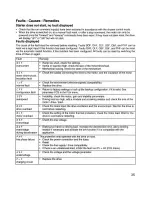
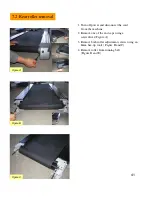
7.2 Rear roller removal

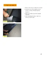
Figure A

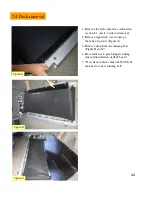
Figure B

1. Turn off power and disconnect the cord 

from the machine

2. Remove one of the end caps using a

screwdriver (Figure A)

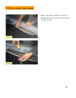
3. Remove both roller adjustment screws using an

8mm hex-tip tools ( Figure B and C)

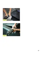
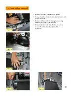
4. Remove roller from running belt 

(Figure D and E)

Figure C

Summary of Contents for MX-T3x

Page 1: ...1 MX T3x TM94E AC SYSTEM SERVICE MANUAL...

Page 2: ...heck list 4 2 Recommended cleaning tips 4 3 Deck and belt replacement 4 4 Check for damaged parts 4 5 Adjusting the belt 4 6 Clean the grooves procedures SECTION 5 MANAGER MODE SECTION 6 TROUBLESHOOTI...

Page 3: ...moval 7 4 Deck Removal Replacement 7 5 Deck cushion replacement 7 6 Front roller removal 7 7 Running belt replacement 7 8 Incline power board removal 7 9 Inverter removal 7 10 Motor Removal 7 11 Drive...

Page 4: ...4 SERIAL NUMBER LOCATION SECTION 1...

Page 5: ...5 Matrix T3x TM94E Serial Number Location...

Page 6: ...6 MOVING THE UNIT SECTION 2...

Page 7: ...his unit weights 487 lbs 221 kgs pounds Be sure to have proper assistance to remove and move the unit to avoid injury to the user and the unit Frame 1 Treadmill Base 2 Console Supports 3 Hardware Fast...

Page 8: ...8 IMPORTANT SAFETY I N S T R U C T I O N S SECTION 3...

Page 9: ...oid injury 2 Keep hands and feet clear of moving parts at all times to avoid injury 3 Unsupervised children must be kept away from this equipment 4 Do not wear loose clothing while on equipment 5 When...

Page 10: ...jury To prevent electrical shock never drop or insert any object into any opening Do not remove the console covers Service should only be done by an authorized service technician Never operate the tre...

Page 11: ...current to reduce the risk of electric shock The treadmill is equipped with a cord having an equipment grounding conductor and a grounding plug The plug must be plugged into an appropriate outlet that...

Page 12: ...12 PREVENTATIVE MAINTENANCE SECTION 4...

Page 13: ...ighten Drive Belt Tighten Deck Bolts Inspect Motor Drive Belt Inspect Stop Key Inspect Front Rear Roller Inspect Handlebars Bolts Inspect Clean Handlebars Clean Bottle Holders Inspect Clean Console In...

Page 14: ...he console and side rails after every use 5 Brush away any wax deposits from the deck and belt area This is a common occurrence until the wax is worked into the belt material 6 Be sure to remove any o...

Page 15: ...tem on the market WARNING Do not run the treadmill while cleaning the belt and deck This can cause serious injury and can damage the machine Maintain the belt and deck by wiping the sides of the belt...

Page 16: ...eventative maintenance is the key to smooth operating equipment as well as keeping the users liability to a minimum Equipment needs to be inspected at regular intervals Defective components must be re...

Page 17: ...uching one side do not start the treadmill Turn the bolts counter clockwise approximately one full turn on each side Manually center the belt by pushing the belt from side to side Tighten the bolts th...

Page 18: ...r dirt or dust and clean it 3 Check the grooves in roller pulley for dirt or dust and clean it If dirty grooves in the drive belt motor and roller pulley there will be noises while running Caution 2 C...

Page 19: ...19 SECTION 5 MANAGER MODE...

Page 20: ...ing saved To access the Engineering screens press and hold the ELEVATION UP and SPEED DOWN buttons for three seconds The display will now display Engineering Mode Use the ELEVATION UP or DOWN arrows t...

Page 21: ...e 95 00 5 00 90 00 LIMIT TIME P7 Change the standard KM or Mile MPH UNIT P6 This variable controls the high for limit for the elevation of the TM 200 HIGH ELEVATION P5 This variable controls the low f...

Page 22: ...y total accumulated time TOTAL TIME P9 This variable controls the default weight used in the calorie calculations KRH 180 MPH 400 KRH2 2 MPH 50 KPH80 MPH150 SET WEIGHT P8 Error information OUT OF ORDE...

Page 23: ...23 SECTION 6 TROUBLE SHOOTINGS...

Page 24: ...24 6 1 Electrical block diagram...

Page 25: ...25 6 2 Wire pin definition P01 Console Wire...

Page 26: ...26 P04 Inverter Wire N24 Pulse Board Wire...

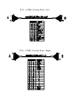
Page 27: ...27 P11 CTRL Overlay Wire Left P12 CTRL Overlay Wire Right...

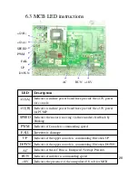
Page 28: ...Indicates if the upper console is commanding Elevation DOWN DOWN Indicates if the upper console is commanding Elevation UP UP Inverter is damage FAIL Indicates if Console is commanding speed PWM Indic...

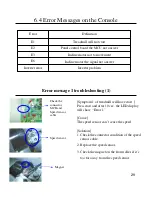
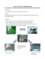
Page 29: ...r Error message 1 troubleshooting 1 Symptom 1 of treadmill will have start Press start and after 10 sec the LED display will show Error 1 Cause The speed sensor can t sense the speed Solution 1 Check...

Page 30: ...olution 1 Open MCB cover connect all cable to Inverter again turn on the power verify the LED indicator of PWM is to glitter If that PWM is not glitter replace console cable 2 If PWM LED also do not g...

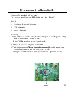
Page 31: ...ard inside parts MCU damage Solution 1 Turn on power again if console still show Error 2 replace PCB 2 Please check the console ground wire whether connect to PCB Please refer the below photo and chec...

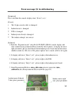
Page 32: ...r please check the between Incline power board and incline motor whether connect is OK if it is OK please replace new console cable to test again 2 If display still show Error 3 or 6 please replace th...

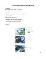
Page 33: ...an t finish Cause 1 Check the connector condition of the speed sensor cable 2 Replace the speed sensor 3 Check the magnet on the front roller if it s too far away from the speed sensor Solution Magnet...

Page 34: ...onsole cable 2 Connector condition of the inverter wire 3 Inverter damage Solution 1 Check the connector condition of the console cable 2 Check the connector condition of the inverter wire 3 Check the...

Page 35: ...35...

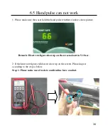
Page 36: ...d pulse whether windows show picture Remark Heart rate figure show up on the screen about in 5 10 sec 2 If the heart rate figure still doesn t show up on the screen Please inspect according to the ste...

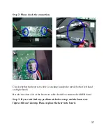
Page 37: ...touching hand pulse metal both of left hand and right hand Besides the other side of the heart rate cable should be connected with HR board Step 3 If you can t find any problem with above step and th...

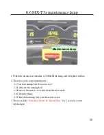
Page 38: ...Test the running belt if loose or not 2 2 Lubricate the running belt 2 3 Remove the motor cover and clean the dust inside 2 4 Clean the frame 2 5 Check the running belt is in the center or not 3 There...

Page 39: ...39 SECTION 7 PARTS REPLACEMENT...

Page 40: ...40 7 1 Plastic shroud removal 1 Remove the front shroud using 4 screws Figure A 2 Front covers are removed Figure B Figure A Figure B...

Page 41: ...n off power and disconnect the cord from the machine 2 Remove one of the end caps using a screwdriver Figure A 3 Remove both roller adjustment screws using an 8mm hex tip tools Figure B and C 4 Remove...

Page 42: ...42 Figure D Figure E...

Page 43: ...ed in section 8 2 2 Loosen the two screws under the end cap reinforce set using a 5mm hex tip tools Figure A 3 Slide the rail off the back of the treadmill Figure B 4 After reinstalling the side rail...

Page 44: ...ction 8 1 and 8 3 side rail removal 2 Remove eight deck screws using a 5mm hex tip tools Figure A 3 Remove deck from the running belt Figure B and C 4 Be careful not to pinch fingers during removal in...

Page 45: ...45 7 5 Deck cushion replacement 1 Remove the deck as outlined in section 8 3 2 Holding the cushion and remove the 13mm nut Figure A and B Figure A Figure B...

Page 46: ...5mm hex tip tools remove the tension set Figure A and B 3 Remove the front roller mounting screws using 8mm hex tip tools Figure C and D 4 Remove the drive belt from the front roller and remove the r...

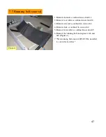
Page 47: ...outlined in section 8 2 3 Remove side rail as outlined in section 8 3 4 Remove deck as outlined in section 8 4 5 Remove front roller as outlined in section 8 5 6 Remove the running belt and replace wi...

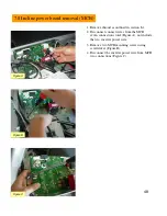
Page 48: ...n 8 1 2 Disconnect connect wires from the MCB seven connections total Figure A not include the two inverter power wire 3 Remove two MCB mounting screws using screwdriver Figure B 4 Disconnect the inve...

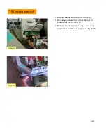
Page 49: ...l 1 Remove shroud as outlined in section 8 1 2 Disconnect connect wires from the inverter connections total Figure A 3 Remove two inverter mounting screws using screwdriver and 6mm hex tip tools Figur...

Page 50: ...on 8 5 3 Cut any wire ties Figure A 3 Disconnect the motor power cable from the inverter Figure B 4 Using the 8mm Allen wrench remove 4 motor mounting screws Figure C 5 Lift the motor away from the tr...

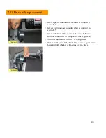
Page 51: ...drive belt as outlined in section 8 5 3 Remove the front roller screw on the drive belt side and loosen the screw on the opposite side Figure A 4 Lift roller and remove old drive belt Figure B 5 Afte...

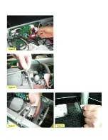
Page 52: ...pin attaching motor shaft to the rack Figure B and C 3 Disconnect the incline motor power cable from the motor control board Figure D 4 Disconnect the pin from the incline motor Figure E 5 Lift the i...

Page 53: ...53 Figure D Figure E Figure F Figure G...

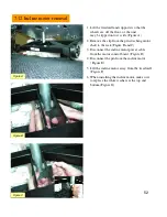
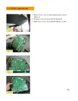
Page 54: ...PCB replacement 1 Remove the two screws from underneath the console Figure A 2 Disconnect the wires from the PCB Figure B 3 Remove the seven screw from PCB Figure C and D Figure A Figure B Figure C F...

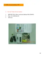
Page 55: ...55 A Service Tools Accessories 1 MSP FET430 Please refer the bulletin NB 0506002 2 Parts NO MT00L 039 3 Software 7 14 PCB software installation SOP...

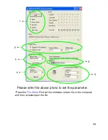
Page 56: ...56 Please refer the above photo to set the parameter Press the File Name Find out the software version file in the computer and then actuate open the file 1 2 4 3 5 6...

Page 57: ...57 Install the MSP430 Tools Computer...

Page 58: ...58 Press the Load Image Installation software to MSP430 Tools...

Page 59: ...59 Installing the MSP430 cable to console MSP430...

Page 60: ...key the MODE light will to glitter about 10 sec If installing pass the OK LET light 2 Drive the machine to provide power for console and then enter into the engineering mode to confirm if the software...

Page 61: ...61 SECTION 8 UPGRADES...

Reviews: