23
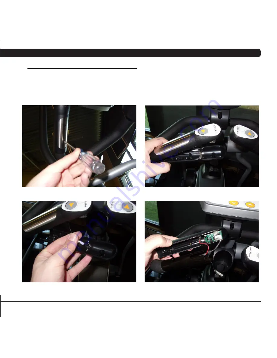
8.3 HeART RATe gRiPS RePlACeMeNT
1) Remove the 3 screws holding the HR grip together (Figure A).
2) Pull the 2 halves of the HR grip apart (Figure B).
3) Disconnect the black wire and remove the lower portion of the HR grip (Figure C).
4) Disconnect the red wire and level button and remove the upper portion of the HR grip (Figure D).
5) Reverse Steps 1-4 to install new HR grips.
6) Test the bike for function as outlined in Section 8.20.
figURe A
figURe B
figURe C
figURe D
CHAPTeR 8: PART RePlACeMeNT gUiDe
Summary of Contents for U3x-01
Page 1: ...U 3 x 0 1 B i k e S E R V I C E M A N U A l...
Page 2: ......
Page 16: ...12 Chapter 7 TROUBLESHOOTING 7 1 Electrical Diagrams...
Page 17: ...13 7 1 Electrical Diagrams Chapter 7 Troubleshooting...
Page 18: ...14 Chapter 7 TROUBLESHOOTING 7 1 Electrical Diagrams P01 Console Cable P03 Pulse Sensor Wire...
Page 50: ...46 step 2 9 3 Assembly Instructions Continued Chapter 9 bike SPECIFICATIONS AND ASSEMBLY GUIDE...
Page 51: ...47 step 3 Chapter 9 Bike specifications and assembly guide 9 3 Assembly Instructions Continued...
Page 52: ...48 step 4 Chapter 9 Bike specifications and assembly guide 9 3 Assembly Instructions Continued...
Page 53: ...49 9 3 ASSEMBLY INSTRUCTIONS CONTINUED Chapter 9 bike specifications and assembly guide Step 5...
Page 61: ...57 NOTES...


