46
9.15 DRIVE BELT REPLACEMENT
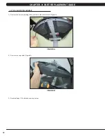
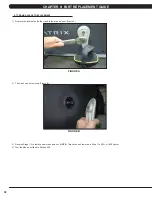
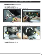
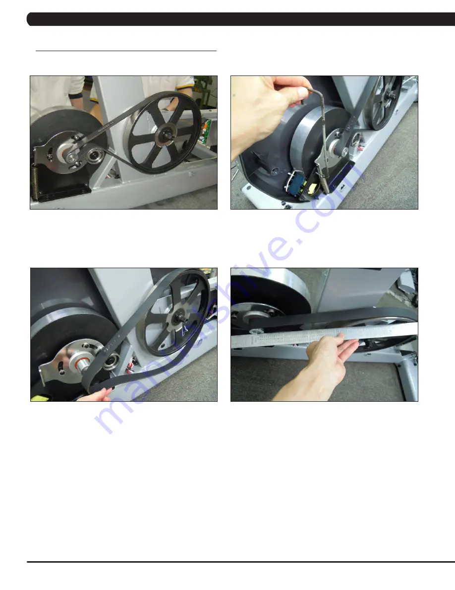
1) Remove the side covers as outlined in Section 9.9 (Figure A).
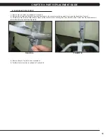
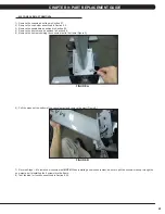
2) Using a hook or loop of wire, remove the spring from the frame (Figure B). The tensioner should now pivot away from the drive belt.
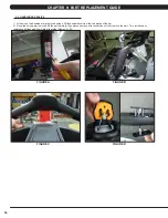
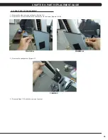
3) Remove the drive belt (Figure C).
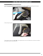
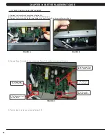
4) Use a straight edge to make sure that the pulley and generator pulley are in a straight line (Figure D). If the belt is not on line, try to adjust
the generator location.
5) Reverse Steps 1-4 to install a new drive belt.
NOTE:
Be sure to reattach the tension spring. Rotate the pulley to make sure that the motion
is smooth and that there is no wobbling to one side.
CHAPTER 9: PART REPLACEMENT GUIDE
FIGURE A
FIGURE B
FIGURE C
FIGURE D
Summary of Contents for U3X-05
Page 1: ...U 3 X 0 5 B I K E S E R V I C E M A N U A L...
Page 4: ...1 1 1 SERIAL NUMBER LOCATION CHAPTER 1 SERIAL NUMBER LOCATION FRAME SERIAL NUMBER LOCATION...
Page 15: ...12 8 1 ELECTRICAL DIAGRAMS CHAPTER 8 TROUBLESHOOTING...
Page 16: ...13 8 1 ELECTRICAL DIAGRAM CHAPTER 8 TROUBLESHOOTING...
Page 19: ...16 8 1 ELECTRICAL DIAGRAMS CONTINUED CHAPTER 8 TROUBLESHOOTING PULSE EXTENDED WIRE...
Page 20: ...17 8 2 LCB LED INDICATORS CHAPTER 8 TROUBLESHOOTING...
Page 73: ...70 NOTES...

