48
CHAPTER 9: PART REPLACEMENT GUIDE
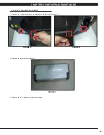
9.17 REAR STABILIZER REPLACEMENT
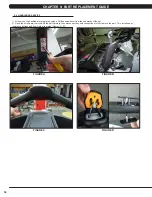
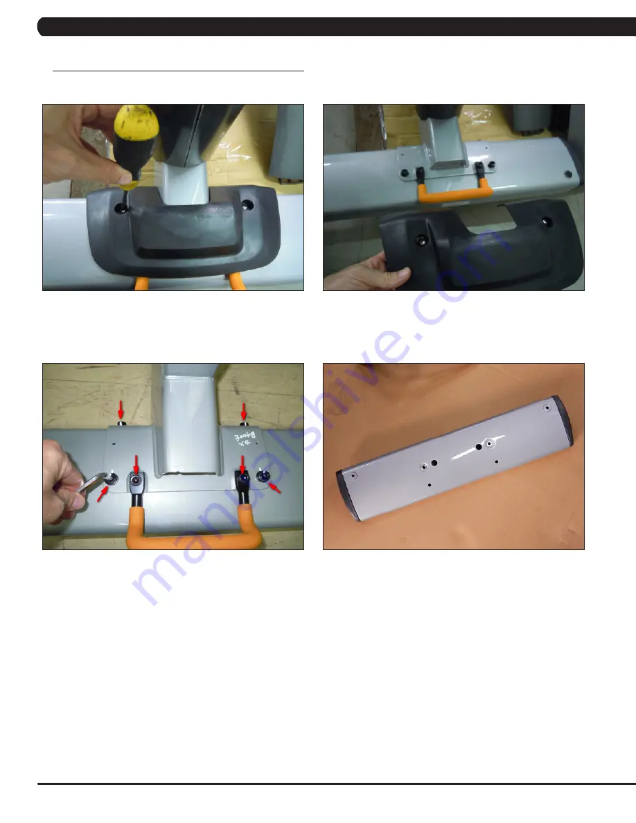
1) Remove the 2 screws holding the black cover to the rear stabilizer (Figure A).
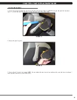
2) Remove the black cover (Figure B).
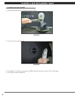
3) Remove the 6 screws holding the rear stabilizer to the frame (Figure C).
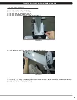
4) Remove the rear stabilizer (Figure D).
5) Reverse Steps 1-4 to install a new rear stabilizer.
NOTE:
When installing a new rear stabilizer, be sure to make sure that the leveling is
stable as outlined in Section 10.4.
FIGURE A
FIGURE B
FIGURE C
FIGURE D
Summary of Contents for U3X-05
Page 1: ...U 3 X 0 5 B I K E S E R V I C E M A N U A L...
Page 4: ...1 1 1 SERIAL NUMBER LOCATION CHAPTER 1 SERIAL NUMBER LOCATION FRAME SERIAL NUMBER LOCATION...
Page 15: ...12 8 1 ELECTRICAL DIAGRAMS CHAPTER 8 TROUBLESHOOTING...
Page 16: ...13 8 1 ELECTRICAL DIAGRAM CHAPTER 8 TROUBLESHOOTING...
Page 19: ...16 8 1 ELECTRICAL DIAGRAMS CONTINUED CHAPTER 8 TROUBLESHOOTING PULSE EXTENDED WIRE...
Page 20: ...17 8 2 LCB LED INDICATORS CHAPTER 8 TROUBLESHOOTING...
Page 73: ...70 NOTES...

