10
4.6 WoRKoUT SETUP STEPS - TARgET HEART RATE
4.7 WoRKoUT SETUP STEPS - CoNSTANT WATTS
CHAPTER 4: CoNSolE oVERlAy AND WoRKoUT DESCRIPTIoN
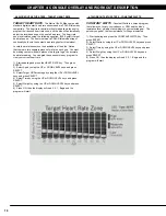
tarGet Heart rate
- The Matrix U5x-04 Bike comes with
standard digital contact heart rate sensors and are POLAR telemetry
compatible. The heart rate control workout mode allows the user to
program their desired heart rate zone, and the bike will automatically
adjust the level based upon the user's heart rate. The heart rate
zone is calculated using the following equation: (220-Age)8%=target
heart rate zone. The user must wear a POLAR telemetric strap or
continually hold onto the contact heart rate grips for this workout.
Locate the metal sensors on the handlebars of the bike. Notice
that there are two separate pieces of metal on each grip. You must
be making contact with both pieces of each grip to get an accurate
heart rate reading. You can grab these sensors in any program to
view your current heart rate.
1) Start pedaling and press the HEART RATE key. Then press
ENTER.
2) Select Age by using the UP or DOWN LEVEL keys and press
SELECT.
3) Select Target HR Percentage by using the UP or DOWN LEVEL
keys and press SELECT.
4) Select Time by using the UP or DOWN LEVEL keys and press
SELECT.
5) Select Weight by using the UP or DOWN LEVEL keys and press
SELECT.
6) Press GO, then the display will read 3, 2, 1, Begin and the
program will start.
constant Watts
- Constant Watts is a unique program
that allows you to vary your cadence or RPM and the bike's
resistance level will adjust accordingly to your selected goal. The
quicker you pedal, the less resistance for the goal selected.
1) Start pedaling and press the CONSTANT WATTS key. Then
press ENTER.
2) Select Watts by using the UP or DOWN LEVEL keys and press
SELECT.
3) Select Time by using the UP or DOWN LEVEL keys and press
SELECT.
4) Select Weight by using the UP or DOWN LEVEL keys and
press SELECT.
5) Press GO, then the display will read 3, 2, 1, Begin and the
program will start.
Summary of Contents for U5x-05
Page 1: ...U 5 x 0 5 B I K E S E R V I C E M A N U A l...
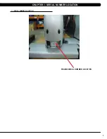
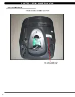
Page 4: ...1 1 1 Serial Number Location Chapter 1 Serial Number Location fRAME Serial number location...
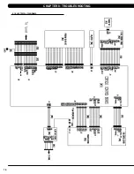
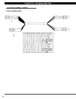
Page 17: ...14 8 1 Electrical Diagrams Chapter 8 Troubleshooting...
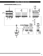
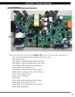
Page 18: ...15 Chapter 8 Troubleshooting 8 1 electrical diagramS CONTINUED...
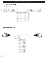
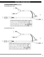
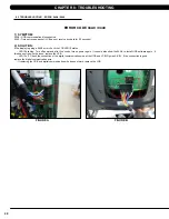
Page 21: ...18 8 1 Electrical Diagrams CONTINUED Chapter 8 Troubleshooting PULSE extended WIRE...
Page 72: ...69 NOTES...


