19
CHAPTER 8: TRoUBlESHooTINg
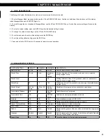
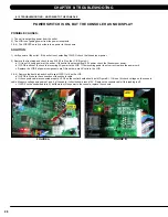
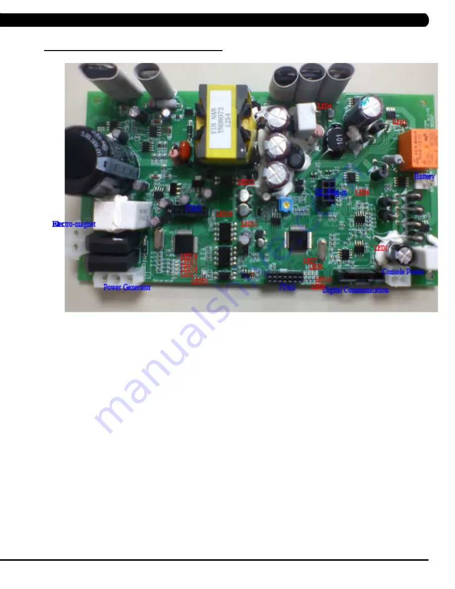
8.2 lCB lED INDICAToRS
============================
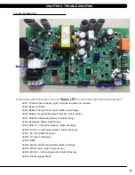
Status LED
=============================
LED1: Console Power Supply. (Light: LCB give the power for console)
LED4: Boost Controller
LED5: Battery Charge Control.(Light : Battery just charge)
LED6: Battery Connection Reverse Protection. Light: reverse
LED7: MCU-B LCB Working Status. (Flash: Working)
LED8: Resistance Offset. Light: Normal
LED9: MCU A <-> B Communication. (Flash: Working)
LED10: UCB <-> LCB Communication. (Flash: Working)
LED11: 5V (For LCB MCU power)
LED12: 12V (For LCB power)
LED13: RPM
LED14: MCU-A LCB Working Status (Flash: Working)
LED15: MCU-A Error (Light: LCB get error)
LED16: MCU A <-> B Communication (Flash: Working)
LED18: Electromagnet PWM
Summary of Contents for U5x-05
Page 1: ...U 5 x 0 5 B I K E S E R V I C E M A N U A l...
Page 4: ...1 1 1 Serial Number Location Chapter 1 Serial Number Location fRAME Serial number location...
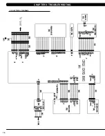
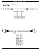
Page 17: ...14 8 1 Electrical Diagrams Chapter 8 Troubleshooting...
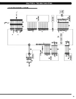
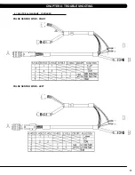
Page 18: ...15 Chapter 8 Troubleshooting 8 1 electrical diagramS CONTINUED...
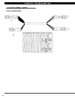
Page 21: ...18 8 1 Electrical Diagrams CONTINUED Chapter 8 Troubleshooting PULSE extended WIRE...
Page 72: ...69 NOTES...


