Mainboard User’s Manual
14
Connect the case switches and indicator LEDs to the
SW1
header.
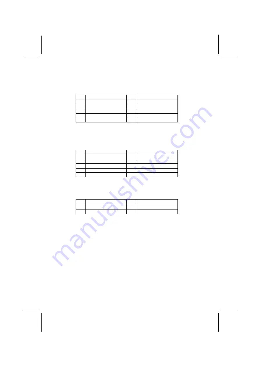
Here is a list of SW1 header’s pin assignments:
Pin Signal
Pin Signal
1
HD_LED_P
2
FP PWR/SLP
3
HD_LED_N
4
FP PWR/SLP
5
RESET_SW_N
6
POWER_SW_P
7
RESET_SW_P
8
POWER_SW_N
9
RSVD_DNU
10
KEY
If there are a headphone jack or/and a microphone jack on the front
panel, connect the cables to the
AUDIO1
header on the mainboard.
Here is a list of AUDIO1 header’s pin assignments:
Pin Signal
Pin Signal
1
AUD_MIC
2
AUD_GND
3
AUD_MIC_BIAS
4
AUD_VCC
5
AUD_FPOUT_R
6
AUD_RET_R
7
HP_ON
8
KEY
9
AUD_FPOUT_L
10
AUD_RET_L
This connector
J1
(LAN LED indicator) is attached to LAN device
that needs a LED indicator.
Pin Signal
Pin
Signal
1
ACT LED
2
ACT LED (+)
3
Link LED (+)
4
Link LED
Summary of Contents for MS8328E Series
Page 4: ...Mainboard User s Manual IV ...
Page 24: ...Mainboard User s Manual 20 ...


