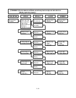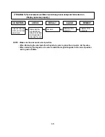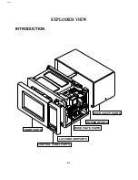
5-9
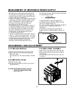
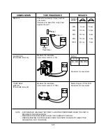
COMPONENTS
TEST PROCEDURE
RESULTS
HIGH VOLTAGE
CAPACITOR
HIGH VOLTAGE
DIODE
NOTE :
Some inexpensive meters
may indicate infinite
resistance in both direction.
Measure the resistance.
(Ohm-meter scale: Rx1000)
• Terminal to terminal.
Measure the resistance.
(Ohm-meter scale: Rx1000)
• Terminal to case.
Measure the continuity (Forward).
(Ohm-meter scale: Rx10000)
Measure the continuity (Reverse).
(Ohm-meter scale: Rx10000)
Normal: Momentarily indicates
several ohms, and
then gradually returns
to infinite.
Normal:
∞
Normal: Continuity.
Abnormal:
∞
Normal:
∞
Abnormal: Continuity.
NOTE: When testing the magnetron, be sure to install the magnetron gasket
in the correct position and be sure that the gasket is in good condition.
Antenna
Gasket
Chassis
Filament
Terminals
Summary of Contents for M130TCS
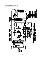
Page 9: ...SCHEMATIC DIAGRAM 4 3 OVEN THERMAL CUT OUT MGT THERMAL CUT OUT ...
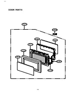
Page 28: ...6 2 13536A 15006A 13552A 13213A 13352A 13720D 14970A 14026A 13581A DOOR PARTS EV ...
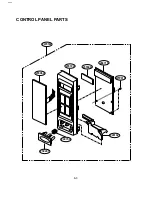
Page 29: ...6 3 24781M 268711 WTP015 250201 23506A 24510L 23572A 24970A 23550D CONTROL PANEL PARTS EV ...
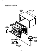
Page 30: ...6 4 34036W 34960A 36549S 33112U WTT021 WTP013 33052A 33390G 35889A OVEN CAVITY PARTS EV ...
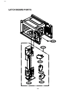
Page 31: ...6 5 466001 43500A 466001 466003 WSZ085 43501A LATCH BOARD PARTS EV ...
Page 33: ...6 7 63303A 63302A WTT021 WSZ002 65006B 56170D 948501 BASE PLATE PARTS EV ...
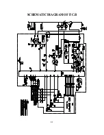
Page 34: ...8 1 SCHEMATIC DIAGRAM OF P C B ...
Page 35: ...8 2 PRINTED CIRCUIT BOARD ...
Page 36: ......

