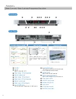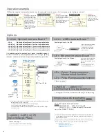
Operation example
Options
Hab shall be required between
REK and personal computer
when control multiple REK via
Ethernet.
-LUs1 : USB Interface Board
*1*2
REK power supply of same model number can be connected in series or parallel to increase output voltage or current.
-LGob : Optical Interface Board + 2 meters long optical cable
-LGob(Fc5) : Optical Interface Board + 5 meters long optical cable
-LGob(Fc10) : Optical Interface Board + 10 meters long optical cable
-LGob(Fc20) : Optical Interface Board + 20 meters long optical cable
-LGob(Fc40) : Optical Interface Board + 40 meters long optical cable
PS1
PS2
+Vout
-Vout
0V
+
-
+
-
Split operation
Vout
+
-
+
-
V1+V2
PS1
V1
PS2
V2
0V
Series operation
Parallel operation
+
-
PS1
PS2
+
-
+
-
Load
[caution]
Remote switch is
connected to–output,
so do not connect to
the other remote switch
simultaneously.
[caution]
Please keep all the settings
of voltage the same. Output
current will be the summation
of each current.
And, please keep OVP level of
power supply maximum to
prevent any damage.
[caution]
Total output voltage is to be
up to 250V. Therefore for
models with output voltage
of over 250V, series operation
cannot be conducted.
Output current is to be the
smallest current of those.
Additionally, the remote
switch is connected to
–output, so do not connect
to the other remote switch
simultaneously.
-L(400V), -L(3P), -L(1P)
Input Voltage, Phase
Please see page 7.
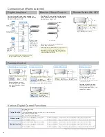
Enable digital control via Ethernet
It is isolated by optical communication. It makes it possible to prevent
malfunction caused by transient phenomenon such as surge, lightning,
induction, and external noise due to perfectly isolated by optical fiber.
B
B
B
32 units can be
connected to 1 CO-G32.
B
32 units can be
connected to 1 CO-E32.
32 units can be
connected to 1 CO-U32.
In case power supply will be use following condition, make sure this options selected.
・
Noisy environment such as factories.
(ex. usage of motor and coil around load or power supply)
・
Usage on high voltage floating (more than 250V)
・
In case the distance between power supply and controller (PC or PLC) is longer
than 2-meter long.
PC
PC
PC
PC
-LGob : Optical Interface Board
*1*2
USB
Ethernet
RS-232C
RS-485
GPIB
hub
hub
Variety of adapters
(Separately sold)
CO-E32
CO-U32
CO-OPT2-25
CO-OPT2-9
CO-OPT4-25
CO-G32
GPIB enables
control of up to
14 CO-G32
modules.
Can be
extended via hub
Can be
extended via hub
CO-opt Cable
Enable digital control via USB
PC
When controlling several REK
power supplies via USB,
a USB hub will be required
between the PC and REK
power supplies.
PC
-LEt : Ethernet Interface Board
*1*2
Single phase AC input cable
(3-pin type)
-L(Mc0.5)
*2
, -L(Mc0.15)
*2
Communication cable extension
A power supply with this option
doesn’t have CE marking.
-LDc : Pulse / Ramp sequence,
Master follow function
-LDe : Pulse / Ramp sequence function
Please see page 5.
The length of CO-M cable will be 0.5-meter long 0.15-meter long.
25A / 250V single phase open terminal
Model
CABLE TYPE 5 : Standard 2.5m length
CABLE TYPE 5( ) : Extended length(1m increment)
<e.g.> 5m : CABLE TYPE 5(5)
separate
*1 If you select this option, standard digital interface and master-slave function will
not be equipped. Also, please see the CO series catalog for detail of function of
digital interface function.
*2 These options cannot be selected together. Only one of each can be selected.
When ordering, suffix the above option number to the model number.
<e.g.> REK30-84-L(Mc0.5)(3P)
REK100-36-LDcGob(Fc20)(1P)
REK500-11-LDeUs1(400V)
(Alphabetical order)
A power supply with this option doesn’t have CE marking.
B
10


