3 Handling
10
DOEF series
Matsusada Precision
3-1 Overview
This product is a high-speed bipolar amplifier that is capable of both positive and negative outputs in CV
mode or in CC mode.
Since it supports four-quadrant output, both source and sink currents can be provided.
Simple controls on the front panel allow you to set sine or square wave output, frequency, and CV or CC
mode. Moreover, it also has a sequence function that allows you to program any waveform to be output.
3-2 Wiring
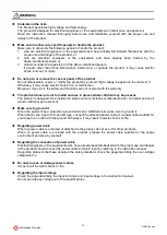
Use electric wire with sufficient thickness, as short as possible.
Use PVC wire with 105-degree heat resistance that withstands working voltage.
Wiring to load must be considered in the current capacity and the length limitation because the
sensing function can compensate only voltage drop up to 0.5V per wire.
Please refer to the following table to determine the thickness of the wire.
AWG
mm
2
Max current [A]
AWG
mm
2
Max current [A]
18
16
14
12
10
8
6
1.1
1.3
2.1
3.3
5.3
8.4
13
2
7
11
18
23
39
67
4
2
1
1/0
2/0
3/0
21
33
42
53
67
85
106
170
209
270
330
350
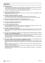
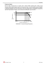
Capacitive load:
Capacitive loads, which have 100pF or more, may cause oscillation.
In that case, insert a power resistor, 1
Ω at 10μF to 1kΩ at 100pF, in series with the output.
Moreover, be careful that the frequency bandwidth is limited depending on the resistance value inserted in
series and the capacity of the capacitive load.
When a power resistor cannot be inserted due to voltage drop or other issues, inserting an inductance
instead of a power resistor may present an equivalent effect. Since this measure also affects the
frequency characteristic as same as the case of inserting a power resistor, select an appropriate one by
monitoring the output waveform.
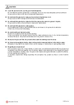
Inductive load:
Some inductance value of an inductive load may cause resonance in CC mode.
In such a case, connect a C-R series circuit between the output terminals to prevent the resonance.
When the output waveform is a sine wave, it may appear as if the output is simply reduced, even though
resonance is occurring.
If an abnormality is suspected, check the output waveform with a sine wave, and then decide whether or
not to add a C-R series circuit.
3 Handling
Current
Time
Time
Normal
square
wave
Resonating square wave
Current
Summary of Contents for DOEF Series
Page 1: ...Instruction Manual F RA 001 3R2 MODEL DOEF series B N 243 9 024 243 9 024 Rev 0 4 ...
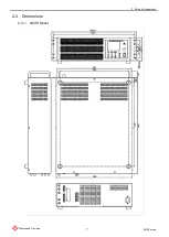
Page 15: ...2 External Appearance 7 DOEF series Matsusada Precision 2 3 Dimensions 2 3 1 400W Model ...
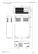
Page 16: ...2 External Appearance 8 DOEF series Matsusada Precision 2 3 2 600W Model ...
Page 17: ...2 External Appearance 9 DOEF series Matsusada Precision 2 3 3 1200W Model ...
Page 121: ......
Page 123: ......
Page 124: ......

