background image

5  Sequence  Function 


63


DOEF series


Matsusada Precision


5 Sequence Function 


5-1  Overview 


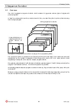
The  unit  is  equipped  a  sequence  function,  which  enables  it  to  generate  various  types  of  outputs  with 
pre-set programs. 
 

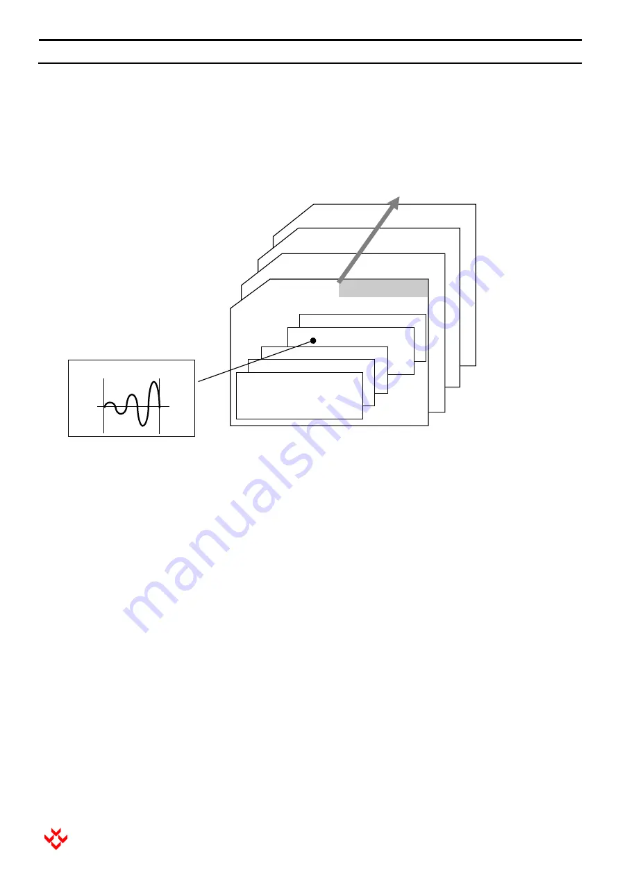
“step” is a unit waveform set for a certain amount of time, so-called “step time” and more than one step 

forms a single program. 


A program is configured with more than one step to form a waveform pattern. 
 
The sequence function is possible to set output waveforms with 1,024 steps in CV mode and CC mode 
respectively.  As  the  number  of  programs  is  also  freely  set  to  one  to  64  in  CV  mode  and  CC  mode 
respectively, it allows the unit to execute multiple programs linked. 
 
For example, when program 1 with 64 steps is finished, execute program 10 with 10 steps, and when the 
program 10 is finished, and then.... Such kind of operation is possible. 
 
As all setting data for step and program are stored in memory, they will remain even if the power of the unit 
is turned off. 
 
Moreover, a large amount of data in CV mode and CC mode with 1,024 steps respectively as well as the 
number of programs and steps are possible to be stored, which has improved easy to use. 


Step    N 

Program 10 

Step 7 

Step N 

Program 1 

Step 1 

Step 2 

Step 3 

Program 25 

Program 4 

A step determines an 
output waveform for a 
certain 

amount 

of 

time 

Linking programs to execute. 

Summary of Contents for DOEF Series

Page 1: ...Instruction Manual F RA 001 3R2 MODEL DOEF series B N 243 9 024 243 9 024 Rev 0 4 ...

Page 2: ...prove its high quality products the information contained in this manual is subject to change without notice Every precaution has been taken in the preparation of this manual Nevertheless Matsusada Precision assumes no responsibility for errors or omissions Neither is any liability assumed for damages resulting from the use of the information contained in this publication Trademarks Company names ...

Page 3: ...oducts Indicates a potentially hazardous situation which if not avoided may result in serious injury or death Indicates a potentially hazardous situation which if not avoided may result in minor or moderate injury or in property damage Indicates danger warning caution Refer to the instruction manual when this symbol appears on the unit Frame or chassis terminal Indicates the possible danger of ele...

Page 4: ...ty The product does not suit to install and use in places where children may be present The product is designed to be installed in places such as factories or laboratories Do not install and use it where children may be present Make sure to ground it When the product has a protection ground terminal or GND terminal make sure to ground it When the AC line input of it is an inlet type connect the at...

Page 5: ...ion Operate the product with the right hand Use only your right hand to operate the product and keep your left hand away from it which can reduce the risk of electric current flowing through the left hand to the vital organs of the body in the event of an electric shock Do not touch the wiring load connected to the output and any terminals connectors during the operation or just after turning outp...

Page 6: ...ecure 30 cm space at least around the openings If they are blocked the product cannot show the rated performance due to the internal temperature increase Moreover components deteriorate and it may result in smoke or fire Remove wiring to and from the product when work like welding near it is done Do not wipe the equipment with a dust cloth wet with chemicals thinner or the like or water Otherwise ...

Page 7: ... 9 3 Handling 10 3 1 Overview 10 3 2 Wiring 10 3 3 Connecting the AC Input Cable 11 3 4 Protection 11 3 4 1 Overvoltage Protection OVP 11 3 4 2 Overcurrent Protection OCP 11 3 4 3 Sink Power Protection 12 3 5 Output Range 12 3 6 Other Functions 13 3 6 1 Output for Voltage Monitor and Current Monitor 13 3 6 2 External Signal 13 3 6 3 Analog Remote Function 13 4 Operation 14 4 1 Basic Operation 14 4...

Page 8: ... 82 6 2 Master Slave Operation Procedures 83 6 3 How to Operate Master Slave 85 6 4 Master Slave Protective Operation 90 6 5 Cautions in Master Slave Operation 92 7 Synchronized operation option Synchronous trigger and synchronous clock 93 7 1 Synchronous trigger 94 7 1 1 Connecting Synchronous Trigger 94 7 1 2 Setting Synchronous Trigger 96 7 1 3 Applications for Synchronous Trigger 97 7 2 Synchr...

Page 9: ... the accessories are different missing or broken please contact us immediately Accessories AC input cord 1 pc Instruction manual 1 pc For option Instruction manual 1 pc CO OPT cable for LGob 1 pc 1 3 Initial Inspection After unpacking check the product for any damage caused by handling or transportation such as scratches dents or other damage before wiring If you find any damage please contact the...

Page 10: ...ith the guide rails of a rack when installing the unit Never support the unit only with the mounting holes on the front panel The handles on the front panel are used to change the direction of the unit or pull out the unit mounted in a rack Avoid any application that the entire weight of the unit is applied to the handles on the front panel 1 5 2 Ventilation The front and back sides of the unit ar...

Page 11: ...to 5 times wider frequency bandwidth is required and around 10 times wider one is required in case of using in square waves in general Inadequate bandwidth causes not only decrease in the output amplitude but much difference between the input and output phases Therefore use the unit while monitoring the output waveform Output swing Vpp Frequency ratio against fc Declination of output swing by freq...

Page 12: ...nce 4 DOEF series Matsusada Precision 2 External Appearance 2 1 External Appearance 2 1 1 Front Panel 400W model 2 1 2 Front Panel 600W model 2 1 3 Front Panel 1200W model Operation panel Operation panel Operation panel ...

Page 13: ...witch 16 SQC sequence switch 5 DIAL 11 DC ACDC switch 6 CANCEL switch 12 Under movement switch 2 2 2 Rear Panel 400W model 19 AC input terminal 25 Sync clk input terminal Option 20 Output terminal 26 Sync clk output terminal Option 21 Voltage monitor terminal 27 Sync trigger connector Option 22 Current monitor terminal 28 Communication connector Option 23 External signal terminal 29 Master slave c...

Page 14: ... input terminal Option 20 Output terminal 26 Sync clk output terminal Option 21 Voltage monitor terminal 27 Sync trigger connector Option 22 Current monitor terminal 28 Communication connector Option 23 External signal terminal 29 Master slave connector Option 24 Analog remote connector 24 29 28 21 22 23 25 26 20 19 26 25 23 22 21 20 29 24 28 19 ...

Page 15: ...2 External Appearance 7 DOEF series Matsusada Precision 2 3 Dimensions 2 3 1 400W Model ...

Page 16: ...2 External Appearance 8 DOEF series Matsusada Precision 2 3 2 600W Model ...

Page 17: ...2 External Appearance 9 DOEF series Matsusada Precision 2 3 3 1200W Model ...

Page 18: ...7 85 106 170 209 270 330 350 Capacitive load Capacitive loads which have 100pF or more may cause oscillation In that case insert a power resistor 1Ω at 10μF to 1kΩ at 100pF in series with the output Moreover be careful that the frequency bandwidth is limited depending on the resistance value inserted in series and the capacity of the capacitive load When a power resistor cannot be inserted due to ...

Page 19: ...onse time of the output cutoff protection is several hundred milliseconds another high speed voltage limit protection works at 110 of the rating to protect the unit and load Voltage limit protection Setting range 0 1 to rated value x 110 for positive and 0 1 to rated value x 110 for negative Setting unit 0 1V Output cutoff protection Setting range 0 1 to rated value x 110 3 4 2 Overcurrent Protect...

Page 20: ...ower consumed in the unit it does not prevent the power consumed in the load The protection works by comparing the effective power value calculated by multiplying the measured effective voltage value by the effective current value with the set suction power protection value Sink power protection Setting range 1 to 300W for 600W model 1 to 600W for 1200W model Setting unit 0 1V 3 5 Output Range Alt...

Page 21: ...al signal to output There is an input terminal on the rear panel for it When 5V is input to it the output of the unit will be the rated voltage or current The output impedance is 1kΩ For details refer to 4 1 Basic Operation 10 External signal in Main Set 2 3 6 3 Analog Remote Function The unit has an analog remote function which allows you to operate and set it by external input signals For exampl...

Page 22: ...rectly if the wiring is done while the POWER switch sets to ON If the start up screen lasts for 20 seconds or more Although the unit checks the memory in the self check if an abnormality is found during it the memory will be initialized It will take approx 20 seconds Do not set the POWER switch to OFF during it Otherwise the memory is not correctly initialized Such abnormality may occur by the POW...

Page 23: ...and AC DC mode is switched while the output is ON the unit will turn off the output for safety Moreover it is not allowed to shift to sequence operation while the output is turned ON If the LED is blinking LS function is enabled and the output is available at any time Short circuiting the LS signal to common will turn the output ON When the LS function is not used disable it If FAULT is displayed ...

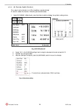
Page 24: ...displays the present status at the top of the screen the settings in the left under it and measurement results in the right under it Fig Layout of the screen Matsusada DCV ACV Freq Wave Sphs ZeroPhs MSR SET MORE LOC Lock 10 000V 20 0V 1 00kHz SINE 0 0deg ON Vdc 10 003 V Vrms 14 138 V Irms 14 146 A Idc 9 997 A AC ANA CV DC FAULT E24 OCP Main Set1 Present status Such as Local Remote CV CC mode and D...

Page 25: ...e always displayed 1 Main Set1 In the box voltage current frequency waveform and measurement setting are displayed State of analog remote ANA Analog mode is enabled State of keylock Lock Key is locked Mode setting DC DC mode AC DC AC DC mode Mode setting LOC Local mode REN Remote mode Mode setting CV CV mode CC CC mode Fault and warning status Matsusada DCV ACV Freq Wave Sphs ZeroPhs MSR SET MORE ...

Page 26: ...ft stop In the box the settings of the soft start or soft stop are displayed Matsusada Ext Signal Soft Start Soft Stop System Response Sense Sync Trig Sync Clk LOC OFF FAST OFF OFF DEN Vdc 10 003 V Vrms 14 138 V Irms 14 146 A Idc 9 997 A AC CV DC Main Set2 Main Set2 Soft Start ON Time 0000s 001 0ms DCV Ramp StartV 10 000V EndV 10 000V ACV Const StartV 20 0V EndV 0V FRQ Sweep StartF 10 00kHz EndF 1...

Page 27: ...s of the protection are displayed Matsusada Save Time Communi BaudRate Terminate Address Command LD LS LOC 80s 9600 CR 0 MTP DEN EN Vdc 10 003 V Vrms 14 138 V Irms 14 146 A Idc 9 997 A AC CV DC SYSTEM System Matsusada PROT Vlim Vlim Ilim Ilim OVP OCP OPP LOC CutOff 22 0V 22 0V 22 0A 22 0A 22 0V 22 0A 200W Vdc 10 003 V Vrms 14 138 V Irms 14 146 A Idc 9 997 A AC CV DC Protect Protect ...

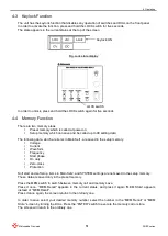
Page 28: ... CANCEL switch Discards the current setting data and returns to the previous setting ENTER switch Accepts and saves the data in change It is also used to shift through the screen CV CC PROT SQC DC AC DC MEM SET SAVE LOCK CV CC switch PROT switch SQC switch DC ACDC switch Downward movement switch in setting Leftward movement switch in setting Memory switch SET SAVE switch Upward movement switch in ...

Page 29: ...text or value of the setting item will be highlighted 2 Protection Settings In order to apply any changes to protection items press the PROT switch the current screen will be switched Likewise the changeable text will be highlighted D C V A C V F r e q 2 0 0 0 0 V 2 0 0 V 1 0 0 k H z D C V A C V F r e q 2 0 0 0 0 V 2 0 0 V 1 0 0 k H z P R O T V l i m V l i m C u t O f f 2 2 0 V 2 2 0 A P R O T V l...

Page 30: ...el In order to cancel any changes while the settings are being changed press the CANCEL switch in Main Set1 screen The waveform settings and voltage current settings can be restored to the previous settings On other than the Main Set1 screen the screen just returns to the previous page and the chancel does not function In order to cancel any changes make sure to press the CANCEL switch when the Ma...

Page 31: ...o save changes in the protection items press the PROT switch again After the setting data is saved the screen will return to the previous one b Cancel Protection settings cannot be canceled Make sure to press the PROT switch to save the settings PROT switch Saves settings by pressing it ...

Page 32: ...een setting items press the downward movement switch or upward movement switch D C V A C V F r e q 2 0 0 0 0 V 2 0 0 V 1 0 0 k H z Downward movement switch Moves to the below item by pressing it Upward movement switch Moves to the above item by pressing it D C V A C V F r e q 2 0 0 0 0 V 2 0 0 V 1 0 0 k H z Downward movement switch Upward movement switch ...

Page 33: ... digit press the leftward movement switch or rightward movement switch 2 0 0 0 0 V 2 0 0 V 1 0 0 k H z D C V A C V F r e q Leftward movement switch Moves to the left digit by pressing it Rightward movement switch Moves to the right digit by pressing it 2 0 0 0 0 V 2 0 0 V 1 0 0 k H z D C V A C V F r e q Leftward movement switch Rightward movement switch ...

Page 34: ...ting up Display contents are switched between CV mode in which DC and AC voltage can be set and CC mode in which DC and AC current can be set Both modes have memory areas respectively Therefore the settings will not disappear even if the mode is switched Fig CV mode Fig CC mode CV CC switch This shows the current mode CV This shows the setting item DC and AC voltage The unit is V This shows the cu...

Page 35: ...ot be switched in the process of setting up In DC mode the settings for AC such as voltage current frequency and waveform are not allowed Fig AC DC mode Fig DC mode DC ACDC switch This shows the current mode ACDC In the case of AC DC mode The AC setting items are displayed and possible to be set This shows the current mode DC In the case of DC mode The AC setting items are not displayed and imposs...

Page 36: ...rating x 105 Setting unit 0 001 mV 0 001 mA The display items and units of the setting values vary depending on the selected mode CV or CC Fig DC voltage setting in CV mode Fig DC current setting in CC mode DIAL Increases or decreases the value of the digit Turn it clockwise to increase the value and counterclockwise to decrease one Leftward movement switch Moves to the left digit by pressing it R...

Page 37: ...o rating x 105 Setting unit 0 1 mV 0 1 mA The display items and units of the setting values vary depending on the selected mode CV or CC Fig AC voltage setting in CV mode Fig AC current setting in CC mode DIAL Increases or decreases the value of the digit Turn it clockwise to increase the value and counterclockwise to decrease one Leftward movement switch Moves to the left digit by pressing it Rig...

Page 38: ...hen the unit operates in the external signal amplifier mode the internal AC waveform signal is not connected regardless of its settings Voltage shift option only for 60 V model When the voltage shift option is installed in the unit the DC voltage setting values and the range differ from the standard mode Refer to 9 Voltage shift Option Voltage or current 0 V or 0 A Peak value Setting value of ACV ...

Page 39: ...an 1kHz and 0 01kHz for 1kHz or more The unit of the displayed frequency and the setting resolution vary between over and lower than 1kHz Fig Over 1kHz Fig Lower than 1kHz DIAL Increases or decreases the value of the digit Turn it clockwise to increase the value and counterclockwise to decrease one Leftward movement switch Moves to the left digit by pressing it Rightward movement switch Moves to t...

Page 40: ...UA Square wave On duty ARB1 Triangle wave None ARB2 Half wave rectification wave sine None ARB3 Instantaneous interruption wave sine None ARB4 Rising exponential function None ARB5 Falling exponential function None ARB6 Step response attenuation 0 1 None ARB7 Impulse response attenuation 0 1 None Fig Sine wave is selected Fig Square wave is selected DIAL Changes waveform settings by turning it Wav...

Page 41: ...nge 0 0 to 360 0 deg Setting unit 0 1 deg On duty Setting range 10 0 to 90 0 Setting unit 0 1 Fig Sine wave is selected Fig Square wave is selected DIAL Increases or decreases the value of the digit Turn it clockwise to increase the value and counterclockwise to decrease one Leftward movement switch Moves to the left digit by pressing it Rightward movement switch Moves to the right digit by pressi...

Page 42: ... current and or frequency will be changed when an AC waveform reaches the zero cross point When the zero cross update is set to off the voltage current and or frequency will be changed at any point In order to set the zero cross update select the item in the Main Set1 and change the setting by turning the DIAL Fig Zero cross update DIAL Changes the zero cross update settings by turning it Wave SIN...

Page 43: ... can be determined by using the equation RMS 2 DC 2 from root mean square values and DC values Vmax Imax Maximum value MAX of voltage current Four The voltage or current that is the maximum among measurements taken for a certain period of time Vmin Imin Minimum value MIN of voltage current Four The voltage or current that is the minimum among measurements taken for a certain period of time A certa...

Page 44: ... the Downward movement switch or Upward movement switch It will be highlighted when selected In the above condition press the ENTER switch The item in the first position will be highlighted With the first position selected turning the DIAL will change the measurement value along with the measurement item ENTER switch DIAL ...

Page 45: ...ewise use the DIAL to set your desired measurement item In order to save the settings press the SET SAVE switch The screen will return to the ordinal display after the setting data was saved When settings other than measurement are continued press the CANCEL switch with a measurement item selected This will bring you back to the MSR SET screen Downward movement switch Upward movement switch CANCEL...

Page 46: ...on the output will be turned off for safety reasons In order to enable or disable the external signal function use the DIAL When the external signal function is enabled the normal measurement may not be possible depending on the input waveform Moreover the protection itself may malfunction because the cutoff protection uses root mean square values Use the limit protection as much as possible when ...

Page 47: ...rating press the OUTPUT switch to force to terminate the operation The setting parameters for the soft start and soft stop are four start value stop value operating time and variation like constant or from start to end For the change rate there are two types as follows Constant The set start value is output for the set period of time The set end value will be ignored Variation Ramp and sweep The o...

Page 48: ... Varying time Range 0 1ms to 1999s 999 9ms Unit 0 1ms Variation Constant Ramp for DC and sweep for AC In order to set the soft start select Soft Start in Main Set2 When selected the text will be highlighted In the state pressing the ENTER switch displays the soft start setting screen Fig Soft Start selected Matsusada Ext Signal Soft Start Soft Stop SYSTEM Response Sense Sync Trig Sync Clk LOC MID1...

Page 49: ...s DCV Ramp StartV 10 000V EndV 10 000V ACV Const StartV 20 0V EndV 0V FRQ Sweep StartF 10 00kHz EndF 1 00kHz LOC AC CV DC Soft Start Soft start setting Enabled Operation time setting DC const ramp setting AC const sweep setting Frequency const sweep setting DC start voltage DC end voltage AC start voltage AC end voltage Freq start Freq end Soft Start ON Time 0000s 001 0ms DCV Ramp StartV 10 000V E...

Page 50: ...ease note that the soft start and soft stop functions are disabled while the unit is operated with communication or analog remote like LS Voltage shift option only for 60 V model When the voltage shift option is installed in the unit the DC voltage setting values and the range differ from the standard mode Refer to 9 Voltage shift Option DIAL Changes setting values Turning clockwise increases valu...

Page 51: ...n Main Set2 When selected the text will be highlighted In the state pressing the ENTER switch displays the setting screen for SYSTEM Fig SYSTEM selected Fig SYSTEM setting Matsusada Ext Signal Soft Start Soft Stop SYSTEM Response Sense Sync Trig Sync Clk LOC OFF OFF FAST OFF OFF DEN Vdc 10 003V Vrms 14 138 V Irms 14 146 A Idc 9 997 A AC CV DC Main Set2 Enter switch Matsusada Save Time Communi Baud...

Page 52: ...n there are several settings below Communication setting Baud rate setting Terminator setting Command setting When LGob option is installed Address setting is also required These settings are required only when the communication option has been installed Regarding the setting of the communication option refer to 5 Communication Option Time for autosave Matsusada Save Time Communi BaudRate Terminat...

Page 53: ...s but those are unavailable In addition parallel and synchronous operation settings are also displayed but these are available only when options are installed Matsusada Ext Signal Soft Start Soft Stop SYSTEM Response Sense Sync Trig Sync Clk LOC OFF FAST OFF OFF DEN Vdc 10 003V Vrms 14 138 V Irms 14 146 A Idc 9 997 A AC CV DC Main Set2 Settings for extension Unchangeable Settings for options ...

Page 54: ...fts to fault state Door switch Interlock Works when the door switch opens Over temperature protection Works when the internal temperature of the unit is equal to or greater than the set temperature 4 2 2 Protection Systems Limit protection Limits voltage or current to the set value The output is not turned off The limit value can be set to positive and negative respectively and can be used for ove...

Page 55: ...Sink power exceeds the set value INTERLOCK Fault Interlock is activated FAULT E02 OT Fault Over temperature protection is activated 4 2 4 Fault Release Press the OUPUT switch to release the fault state In addition sending a LS signal or communication command to turn on the output is also possible to release the fault state When over temperature protection has been activated Turn off the unit and w...

Page 56: ...nge 0 1 to rating x 110 Setting unit 0 1 V Setting of cutoff protection for overvoltage Setting range 0 1 to rating x 110 Setting unit 0 1 V Setting of limit protection for overcurrent Positive Setting range 0 1 to rating x 110 Setting unit 0 1 A Negative Setting range 0 1 to rating x 110 Setting unit 0 1 A Setting of cutoff protection for overcurrent Setting range 0 1 to rating x 110 Setting unit...

Page 57: ... and set the figure by turning the DIAL Matsusada PROT Vlim Vlim Ilim Ilim OVP OCP OPP LOC Cutoff 22 0V 22 0V 22 0A 22 0A 22 0V 22 0A 200W Vdc 10 003V Vrms 14 138 V Irms 14 146 A Idc 9 997 A AC CV DC Protect PROT switch DIAL Changes setting values Turning clockwise increases value and counterclockwise decreases value Leftward movement switch Moves to the left digit by pressing it Rightward movemen...

Page 58: ...he setting value and range for DC voltage are different Refer to 9 Voltage Shift Option Protection system for overvoltage and overcurrent Limit protection or cutoff protection Positive limit setting value for overvoltage Negative limit setting value for overvoltage Positive limit setting value for overcurrent Negative limit setting value for overcurrent Cutoff setting value for overvoltage Cutoff ...

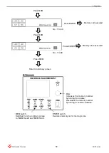
Page 59: ...g data which are items in Main Set1 are saved in the setup memory Voltage Current Waveform Frequency Start phase On duty Zero cross Protection Soft start and soft stop items in Main Set2 and SYSTEM settings are not saved in the setup memory These data are saved only in the preset memory Press the MEM switch to switch between memory call and memory save Press it once MEM Recall appears in the curre...

Page 60: ...ss ENTER Memory store executed MEM switch Switches from the ordinary screen to MEM Recall and MEM Store ENTER switch Executes memory call or memory store DIAL Increases the memory number by turning it clockwise Decreases the memory number by turning it counter clockwise Press MEM Press MEM Return to ordinary screen ...

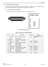
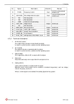
Page 61: ...le Pin assignment and signal description No Signal Description Direction Remark 1 ACVCON AC voltage current control Input 0 to10V analog signal ACOM level 2 NC Not connected 3 ACOM Common of analog signals 4 LD Interlock Input COM level 5 FRQ_EN Frequency control enabled Input COM level 6 NC Not connected 7 NC Not connected 8 STEP_BIT1 Step output bit 1 Output COM level 9 DC_POLE Setting signal of...

Page 62: ...5 DCAC_SET setting signal of DC DCAC mode Input COM level 4 5 2 Functional Description 1 LS Remote switch The output can be turned on and off with the signal In order to use the function enable it via the operating panel 2 LD Interlock The interlock function is available with the signal In order to use the function enable it via the operating panel 3 Output status The output state ON or OFF is out...

Page 63: ...m setting screen Fig SYSTEM selected 2 Select LS in the SYSTEM setting screen using the downward movement switch 3 Set EN by turning the DIAL 4 After the setting is complete press the SET SAVE switch to save the change Fig LS function setting Matsusada Ext Signal Soft Start Soft Stop SYSTEM Response Sense Sync Trig Sync Clk LOC OFF FAST OFF OFF DEN Vdc 10 003V Vrms 14 138 V Irms 14 146 A Idc 9 997...

Page 64: ... close to turn on the output Open to Close The output is turned on OUTPUT LED blink on Close to Open The output is turned off OUTPU LED blink How to enable the LS function a Set LS to EN while the LS signal is opened In this case the OUTPUT LED will blink b Set LS to EN while the LS signal is closed In this case the OUTPUT LED will not blink and the output is in off state In the state open the LS ...

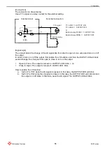
Page 65: ... Connection The connection is shown below Use a TTL signal or a relay contact for the external setting Signal logic Open Abnormal The unit is in a fault state Close Normal How to clear the fault state a Close the external relay for LD or set the TTL signal for it to low and then press the OUTPUT switch b In the case where the LS signal has been used first close the external relay for LS or set the...

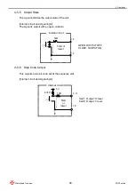
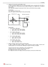
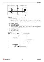
Page 66: ...nd signal logic The signal is output with an open collector 4 5 6 Step Code Output This outputs a two bit code set at the sequence edit Internal circuit and signal logic 1kΩ 5 mA or lower Internal circuit OPEN OUTPUT OFF CLOSE OUTPUT ON 19 18 Set 1 Output H level Set 0 Output L level 18 10Ω Internal circuit 5mA or lower 4 7kΩ 5V 8 21 ...

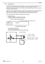
Page 67: ...in 10 DCAC _EN and pin 24 VCON_EN When they are not enabled the unit operates with preset or default settings and values Input control signals after enabling the settings and setting values a ANA_RMT signal It enables or disables the analog remote function To enable the function connect the signal to COM Fig Analog remote is enabled Connection and signal logic The connection is shown below Use a T...

Page 68: ... DCAC_EN signal Low or close DCAC_SET enabled High or open DCAC_SET disabled Pin 13 CVCC_SET signal Low or close CC mode High or open CV mode Pin 25 DCAC_SET signal Low or close DC mode High or open ACDC mode c Setting of Voltage current frequency and DC polarity In order to enable the setting of voltage current frequency and DC polarity connect each enabling signal to pin 18 COM After enabling ea...

Page 69: ... 24 VCON_EN signal Low or close Enabled High or open Disabled When this signal is enabled the text color for the voltage current setting value in the screen will change from white to black Pin 9 DC_POLE signal Low or close Negative High or open Positive Connection 18 5 24 9 External relay COM COM TTL signal 5kΩ 100Ω External connection Internal circuit External voltage Analog COM Internal circuit ...

Page 70: ... Output 1kHz Input 10V Output 200kHz Pin 15 DCVCON signal CC voltage current Input 0V Output rating x 0 Input 10V Output rating x 105 The polarity is switched with the pin 17 DC_POLE signal When analog signals are input the text of the currently enabled setting values will be displayed in black Set each value while checking the displayed values Furthermore analog signals linearly change as shown b...

Page 71: ...et to one to 64 in CV mode and CC mode respectively it allows the unit to execute multiple programs linked For example when program 1 with 64 steps is finished execute program 10 with 10 steps and when the program 10 is finished and then Such kind of operation is possible As all setting data for step and program are stored in memory they will remain even if the power of the unit is turned off More...

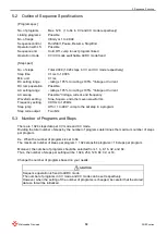
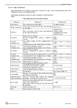
Page 72: ...cy Waveform setting Sine Square and other seven waveforms Frequency setting 0 01Hz to 120kHz Step jump Off or 1 to 999 Jump to the set step in a program Step code output Two bits 5 3 Number of Programs and Steps There are 1 024 steps data per CV mode and CC mode Dividing the total number of steps by the number of programs determines the maximum number of steps per program Ex When the number of pro...

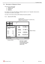
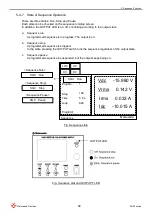
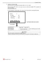
Page 73: ...he screen is also used to call a program The other 2 to 4 screens is used to edit the settings of sequence programs 5 4 1 Sequence Run Stop SQC Run Matsusada Prog No Step Time Loop Prog Edit LOC 1 104 5 6 s 846 Vdc 15 980 V Vrms 0 142 V Irms 0 033 A Idc 10 015 A AC CV DC Sequence Current status State of CV or CC mode DC or ACDC mode remote or local mode etc Measurement Sequence condition Run Stop ...

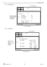
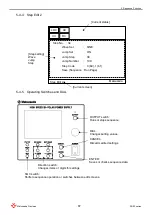
Page 74: ...am Data LOC AC CV DC Sequence Program setting End step number Loop number End setting Current status Matsusada Current screen Step No 34 Time 0000s 001 0ms DCV Ramp StartV 10 000V EndV 10 000V ACV Const StartV 20 0V EndV 0V FRQ Sweep StartF 10 00kHz EndF 1 00kHz LOC AC CV DC Step Edit 1 Step setting Time Voltage Current Ramp Sweep Current status Matsusada Current screen ...

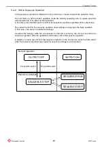
Page 75: ...0 b0 1 b1 Save Sequence Run Page LOC AC CV DC Step Edit 2 Step setting Wave Jump Step Current status Matsusada Current screen OUTPUT switch Runs or stops sequence DIAL Changes setting values ENTER Saves or checks sequence data CANCEL Discards edited settings Direction switch Changes items or digits for settings SQC switch Shifts to sequence operation or switches between edit screens ...

Page 76: ...will not shift to the sequence operation while settings are ongoing in the basic operation In that case once cancel or finalize the settings As well as the settings while the unit operates in soft start or soft stop the unit will not shift to the sequence operation After the operation is terminated shift to the sequence operation In addition to return the unit from the sequence operation to the no...

Page 77: ...gress The output is on b Sequence stop A programmed sequence is stopped In the state pressing the OUTPUT switch runs the sequence regardless of the output state c Sequence pause A programmed sequence is suspended but the output keeps being on Fig Sequence state Fig Sequence stat and OUTPUPT LED SQC Run Matsusada Prog No Step Time Loop Prog Edit LOC 1 104 5 6 s 846 Vdc 15 980 V Vrms 0 142 V Irms 0 ...

Page 78: ...hange Fig Switches for operation 4 Press the OUTPUT switch to run the sequence program Pause 5 Press the SQC switch to make the program to pause Resume 6 Press the SQC switch to resume the sequence program Stop 7 Press the OUTPUT switch to stop the sequence program while it is running or pauses The output will be off Even when the sequence program has been terminated and the output is held pressin...

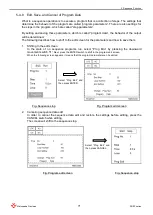
Page 79: ...o shift to the edit screen for the parameters and how to save them 1 Shifting to the edit screen In the state of no sequence programs run select Prog Edu by pressing the downward movement switch Next press the ENTER switch to shift to the program edit screen When the following screen appears it means that the program parameters can be edited Fig Sequence stop Fig Program edit screen 2 Canceling se...

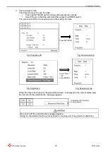
Page 80: ...equence stop after saving the data Fig Program edit Fig Sequence stop Fig Step Edit 2 Fig Sequence stop While the data is being saved Sequence Data Save is displayed in the current status area Do not turn off the unit while the message appears Do not turn off the unit while the message appears Doing so the data will not be correctly stored in memory and it may lead to malfunction Press SET SAVE Se...

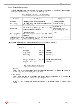
Page 81: ...e program count When it is modified all sequence data will be initialized 1 to 64 Initialization of all program data All sequence data in CV or CC mode will be initialized to factory default The value of the maximum step varies depending on the number of programs Fig Each settings in program edit 1 End step Select End Step on the program edit screen using the downward or upward movement switch Set...

Page 82: ...itch again If you want to cancel the modification press the CANCEL switch Fig Setting of linking program Fig Setting of linking program number 4 Setting the number of programs Set the number of programs in CV or CC mode The setting range is 1 to 64 When the value is modified all step data will be initialized once Select Change Prog Num on the program edit screen using the downward or upward moveme...

Page 83: ...00 End Setting OFF Change Prog Num 64 Program Data Clear Change Prog Num Prog No 3 End Step 32 Loop Number 100 End Setting OFF Change Prog Num 64 Program Data Clear 64 Press CANCEL Press ENTER Press ENTER Fig Change Prog Num selected Fig Changing program number Fig Initializing sequence data ...

Page 84: ...movement switch Press the ENTER switch For the initialization it takes approx five seconds Do not turn off the unit during this period Do not turn off the unit while the message appears Doing so the data will not be correctly stored in memory and it may lead to malfunction Prog No 3 End Step 32 Loop Number 100 End Setting OFF Change Prog Num 64 Program Data Clear Press ENTER Fig Program Data Clear...

Page 85: ...ting x 105 to rating x 105 AC setting Select Const or Sweep AC end voltage current setting is disabled in Const Const Sweep AC start voltage current The steady values for AC voltage current in Const The start values for AC voltage current in Ramp rating x 105 to rating x 105 AC end voltage current The setting is disabled in Const The end values for AC voltage current in Sweep rating x 105 to ratin...

Page 86: ...tep Edit 1 Matsusada Step number Range of step time DC setting AC setting Frequency setting DC start voltage current DC end voltage current AC start voltage current AC end voltage current Start frequency End frequency Step No 34 Wave Set SINE Jump Set ON Jump Step 38 Jump Number 199 Step Code 0 b0 1 b1 Save Sequence Run Page Step Edit 2 Matsusada Step number Waveform Jump setting Step No for jumpi...

Page 87: ...CV or DCI on Step Edit1 1 and select Const or Ramp by turning the DIAL 5 DC start voltage current Select StartV on Step Edit 1 and set a voltage or current value by turning the DIAL The range that can be set rating x 105 to rating x 105 6 DC end voltage current The setting will be ignored in Const Select EndV on Step Edit 1 and then set a voltage or current value by turning the DIAL The range that...

Page 88: ...lect waveform by turning the DIAL 14 Jump setting There are two options ON and OFF When ON is selected it will jump to the specified destination step When OFF is selected it will not jump but just go to the next step Select Jump Set on Step Edit 2 and set it by turning the DIAL 15 Step number for jumping destination Set your desired step number for jumping destination Select Jump Step on Step Edit...

Page 89: ...g Sequence stop While the data is being saved Sequence Data Save is displayed in the current status area Do not turn off the unit while the message appears Do not turn off the unit while the message appears Doing so the data will not be correctly stored in memory and it may lead to malfunction Select Save and press ENTER It indicates that the data is being saved ...

Page 90: ... The following sections describe the differences in operation display and behavior between master slave operation and standalone operation 6 1 Connecting Master and Slave Units Prepare the provided master slave connection cable Since the D sub cover of the cable is labeled like Master Slave1 and Slave2 please connect the cable connector to the M S connector D sub 15 pin female on the rear panel of...

Page 91: ...mally if two slave units are set to Slave Unit1 or Slave Unit2 After saving the settings turn off the POWER switch on the slave units Step 3 Turning on the power switch on the master unit and setting up the number of slaves to the master unit Turn on the POWER switch on the master unit to start it up Since the master unit has an item for setting up the number of slave units set the number of slave...

Page 92: ...master and slave units Max value for output current Max setting value of the master unit x Master unit number of slave units Remarks When soft start soft stop and sequence operations are executed as master slave operation these output settings are performed on the master unit The slave units are not allowed to do so Step 7 Turning the OUTPUT In order to turn on the output press the OUTPUT switch o...

Page 93: ... therefore the current measurement value is the total figure Display on the slave unit Items that cannot be set are displayed as The displayed measurement values are the values measured by the unit including the current values It indicates the master unit All current values displayed are the total of all master and slave units It indicates the slave unit 1 In the case of the slave unit2 SLAVE2 wil...

Page 94: ...ment switch to select MORE and press the ENTER switch to open Main Set 2 Use the downward movement switch to select Slave Unit and set the number of slave units by turning the DIAL Then press the SET SAVE switch to save the setting When the number of slaves is changed be sure to save the settings set the POWER switch to OFF and then set the POWER switch to ON again to restart the unit Without rebo...

Page 95: ...ng On the master unit set the output current value as a single unit Since the slave units follow the setting value the current in the entire master slave unit is as follows Ex When two 20V 20A models are connected as a slave 20A x 105 x master unit two slave units Max 63A Setting via communication When using the communication option only the master unit is connected to a controller via communicati...

Page 96: ... Main Set 2 of the slave unit there is an item for setting the number of slave units In order to perform the master slave operation be sure to set the number of slave units connected first Press the SET SAVE switch to enter the setting state use the downward movement switch to select MORE and press the ENTER switch to open Main Set 2 Use the downward movement switch to select Slave No and set the ...

Page 97: ... with the communication option only the master unit is connected to a controller via the communication and read out the total values across the entire master slave units The slave units are not allowed to use communication function Irms 28 280 A Idc 20 001 A On the other hand the current values of the master unit display the total values Matsusada Vdc 10 006 V Vrms 14 140 V Measured values of the ...

Page 98: ...tective functions during master slave operations the master unit provides voltage and current limit overvoltage protection OVP overcurrent protection OCP and sink power protection OPP to protect the entire master slave and overtemperature protection OT and sink power protection OPP in which each unit protects only itself Even if one of the slave units detects an error the entire master slave units...

Page 99: ...Fault state due to overcurrent Master unit FAULT E22 OVP Fault state due to over voltage Master unit FAULT E23 OPP Fault state due to sink power Each unit OVER POWER State in which sink power is exceeding the setting value Master unit only itself INTERLOCK Fault state due to interlock activated Master unit only itself FAULT E02 OT Fault state due to overtemperature Each unit Ex Display on a unit t...

Page 100: ...s are not available for it Be sure not to connect the master slave connection cable from the slave units not to be operated Even if they have been turned off Be sure not to connect loads to the slave units not to be operated Even if they have been turned off Connect the master and slave units directly to loads through their respective output terminals Do not connect loads via the master or slave u...

Page 101: ... the next synchronous slave unit when the output is on is 0 5μs reference value Sequence operation is also possible to start stop simultaneously The gap for the sequence operation is also 0 5μs reference value For the connection use the D Sub connector on the rear panel Synchronous clock Using a common clock enables the waveform frequency to match each other In addition the step time for sequence ...

Page 102: ...ector on the rear panel to connect the synchronous master unit and the synchronous slave unit Fig Signals and pin assignment for synchronous trigger Pin Assignment Signal name Description Directio n Remarks 1 MOUT Synchronous master unit OUTPUT Output Synchronous master unit 2 SIN Synchronous slave unit OUTPUT Input Synchronous slave unit 3 SOUT Synchronous slave unit OUTPUT Output Synchronous sla...

Page 103: ... 6 and 7 from the synchronous master unit to the synchronous slave unit respectively Also connect the common signal Pin 1 MOUT Pin 2 SIN Pin 3 SOUT Pin 2 SIN Pin 5 TRIG_MOUT Pin 6 TRIG_SIN Pin 7 TRIG_SOUT Pin 6 TRIG_SIN Pin 4 COM Pin 4 COM Pin 8 COM Pin 8 COM Synchronous master unit Synchronous slave unit 1 Synchronous slave unit 2 ...

Page 104: ... SAVE switch to enter the setting state use the downward movement switch to select MORE and press the ENTER switch to switch from Main Set 1 to Main Set 2 Use the downward movement switch to select Sync Trig and set OFF MAS synchronous master unit SLV synchronous slave unit by turning the DIAL Then press the SET SAVE switch to save the setting Synchronous master unit Only one unit set in the synch...

Page 105: ...quence operation When using both sequence operation and the synchronous trigger function set the synchronous trigger before entering Sequence Set In addition when the synchronous master unit performs sequence operation the off state of the output varies depending on the end setting of the sequence operation 1 In the case where the end setting of the synchronous master unit is off As the synchronou...

Page 106: ...seconds the phase shift of one cycle occurs after 5 000 seconds Providing a 10MHz clock using the synchronous clock function can perfectly match the frequency of the generated waveform Similarly the sequence step time and soft start time also match When it is used with the synchronous trigger function the same waveform can be output simultaneously when the same settings are applied to multiple uni...

Page 107: ...he reference unit for the clock and set the synchronous clock function to DEN Disabled and set it in the other units to EN Enabled to operate with the synchronous clock Then connect the clock signal in cascade Input clock 10MHz Clock output 10MHz The input clock is used as the reference clock to generate a waveform The internal clock is not used A clock is output which matches the input clock Inpu...

Page 108: ...et 2 Use the downward movement switch to select Sync Clk and set DEN disabled EN enabled by turning the DIAL Then press the SET SAVE switch to save the setting On communication the synchronization clock needs to be enabled or disabled with the EXTCLK command For details refer to DOEF series communication instruction manual Synchronous clock setting DEN Disabled EN Enabled Fig Main Set 2 Matsusada ...

Page 109: ...ble so that the unit s internal clock is used as the reference one The internal clock is output as the clock output At this time UnLock will appear in the status area and be blinking Fig Unlocked When the clock is connected and set correctly If transitions from the locked to the unlocked state and vice versa were repeated it may cause malfunction i e The input clock cannot be used as the reference...

Page 110: ...o 42 Vpk peak Unit power up on the synchronous trigger operation For synchronous trigger operation turn on the power of both the synchronous master and the synchronous slave units at the same time or turn on the synchronous master unit first and then turn on the synchronous slave units Unit power up on the synchronous clock operation For synchronous clock operation turn on the reference unit and t...

Page 111: ...mmunications a Setting of communication option LUS1 LGOB The setting is fixed at the shipment so it cannot be changed b Setting of baud rate Baud rate 9600 19200 38400 c Setting of the unit number for LGob option Address 0 to 31 d Communication commands Setting of command MTP Matsusada original command SCPI command For details on operations commands etc please refer to the Instruction Manual for o...

Page 112: ... are complete turn off the unit and on again In the case of LUs1 option the setting of the unit number cannot be changed b LGob option Select BaudRate in SYSTEM Set your desired baud rate by turning the DIAL Select Unit No Set the unit number by turning the DIAL Select Command and set it by turning the DIAL After the settings are complete turn off the unit and on again After restarting the unit th...

Page 113: ...he voltage can be set up to 25Vp p Ex When Vlim is set to 5 0V Vlim can be set up to a minimum of 20 0V 9 2 Limiting Output Current The output voltage range affects the output current range In the case of a 60V model it can output up to 100 of the rated current at 60V or lower output voltage but it can only output up to 50 of the rated current at 115V output voltage See the figure next page for DC...

Page 114: ...t Vlim is 60V or less the output current is limited Case of Vlim 115V Vlim 5V Case of Vlim 5V Vlim 115V Output Voltage Negative voltage limit 115V rating x 50 5V Case of Vlim 115V Vlim 5V Case of Vlim 5V Vlim 115V Output Voltage Positive voltage limit Output Voltage Negative voltage limit 60V 115V 115V rating x 100 rating x 50 rating x 100 rating x 50 Output Current Output Current 5V 5V ...

Page 115: ...ue Vlim 5 0V to 115 0V 0 1V to 66 0V Voltage cutoff value 0 1V to 115 0V 0 1V to 66 0V 9 4 Setting Protection System In the DOEF series the limit or cutoff protection can be selected but models with the voltage shift option limit protection will also operate at the same time since voltage shift is performed even if cutoff protection is selected The setting procedures are the same as 4 2 Operation ...

Page 116: ...artV DC end voltage EndV Determine the output range in the voltage limit protection setting and then set the DC voltage Even if the DC voltage is set beyond the output voltage range set by the voltage limit protection the voltage outside the output range will not be output 9 6 Display Digit and Resolution for Voltage Measurement For models with and without the voltage shift option the display digi...

Page 117: ...oltage setting DCVSET 0 01V 115 00V 115 00V 5 digits Positive voltage limit VULIM 0 1V 5 0V 115 0V 4 digits Negative voltage limit VLLIM 0 1V 5 0V 115 0V 4 digits Positive current limit IULIM 0 1A 0 1A 60 to 110 of rating current 1 4 digits Negative current limit ILLIM 0 1A 0 1A 60 to 110 of rating current 2 4 digits Voltage cutoff OVPSET 0 1V 0 1V 115 0V 4 digits Voltage effective value readout V...

Page 118: ...digits Positive voltage limit SOURce VOLTage PROTect UPPer 0 1V 5 0V 115 0V 4 digits Negative voltage limit SOURce VOLTage PROTect LOWer 0 1V 5 0V 115 0V 4 digits Positive current limit SOURce CURRent PROTect UPPer 0 1A 0 1A 60 to 110 of rating current 1 4 digits Negative current limit SOURce CURRent PROTect LOWer 0 1A 0 1A 110 to 60 of rating current 2 4 digits Voltage cutoff SOURce VOLTage PROTe...

Page 119: ... for soft start SSTArt DCVEnd Start DC voltage for soft stop SSTOp DCVStart End DC voltage for soft stop SSTOp DCVEnd Each step DC voltage for sequence SEQuence EDIT STEP DCVSET Positive voltage limit 60V SOURce VOLTage PROTect UPPer Negative voltage limit 60V SOURce VOLTage PROTect LOWer Positive current limit 110 of rating SOURce CURRent PORTect UPPer Negative current limit 110 of rating SOURce ...

Page 120: ...tems They are not always a failure in the following cases check the unit once again before requesting our services Problem Items to check No output or the output does not meet the preset value Is the input voltage within the specifications 400W models 100 to 240Vac 50 60Hz single phase 600W 1 2kW models 200 to 240Vac 50 60Hz single phase Is the wiring correct ...

Page 121: ......

Page 122: ...Revision History Rev No Rev Date Revision Contents 0 0 2016 05 First edition 0 4 2020 10 Added Revision History Added Note and Warranty Corrected spelling mistakes Applied new format ...

Page 123: ......

Page 124: ......

Reviews: