4
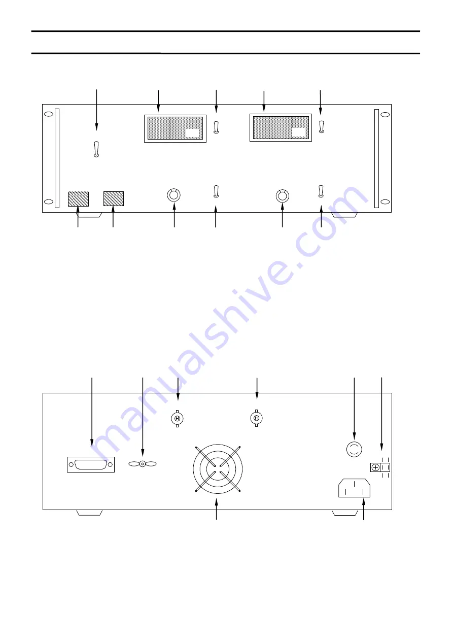
Front panel
Rear panel
2
Exterior view diagram
2 Exterior view diagram
① POWER ON/OFF switch
② HV ON/OFF switch
③ CH① Output setting dial
④
CH② Output setting dial
⑤
CH①(Output voltage meter, Current meter)
⑥
CH②(Output voltage meter, Current meter)
⑦
Local / Remote change switch
⑧
CH① Voltage, Current display change switch
⑨
CH② Voltage, Current display change switch
⑩
CH① Output polarity change switch
⑪
CH② Output polarity change switch
POWER
HV
⑦
⑤
Adj.
Adj.
REMOTE
LOCAL
kV
mA
⑥
⑧
④
③
②
①
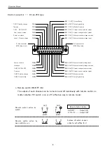
① GROUND terminal
② CH② Output connector
③ CH① Output connector
④ FUSE(7A)
⑤ INPUT AC115V connector
⑥
⑥ Control connector
⑦ Fan
kV
mA
⑤
⑦
②
Vinyl clamp for
AC cord fixation
GND
FUSE
⑥
OUTPUT②
OUTPUT①
④
①
③
CONTROL
CH1
CH2
+
-
+
-
⑪
⑩
⑨
Summary of Contents for EC Series
Page 1: ...Rev 0 6 B N 024 9 005 024 9 005 MODEL EC series Instruction Manual F RA 001 3R0 ...
Page 19: ......
Page 20: ......


