5
3-1 Outline
This unit is a polarity switchable bi-polar high voltage power supply with 2 outputs channels
for electrostatic chuck application.
3-2 Operation method
1.
Upon confirming the connection made with this unit as specified (Refer to 1-4[HOW TO
GROUND]), operate it. Be sure to connect the earth with the ground terminal of the unit.
2.
Connect the attached AC input cord with AC 115V input connector (INPUT AC115V) on the
rear panel and plug socket. (For extra safety fix the cord on the vinyl clamp for cable
fixation.)
3.
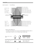
Connect the interlock. (Refer to P7. d. Interlock)
4.
Turn on the POWER Switch. The orange lamp lights on, and the unit gets in stand-by mode.
No high voltage is generated on the output terminal when unit is in this mode.
5.
When the HV ON/OFF switch is turned on, the red lamp lights on, and the unit gets in enable
mode(when local mode).
6.
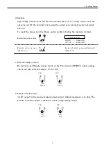
With the output voltage setting dial, set an desired voltage.
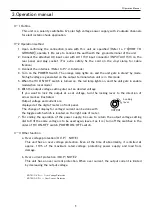
If you want to lock the output at a set voltage, turn the locking lever to the direction of
arrow mark as illustrated.
Output voltage and current are
displayed at the digital-meter on front panel.
The change of display for voltage・current can be done with
the toggle switch which is located on the right side of meter.
7.
For ending the operation of the power supply, be sure to return the output voltage setting
dial to 0 (if the same voltage is to be used again, leave it as it is), turn off the switches in the
order of HV ON/OFF switch, POWER ON/OFF switch.
3-3 Other function
a.Over voltage protection (O.V.P) NOTE 1
This unit has an over voltage protection. Even at the time of abnormality, it is limited at
approx. 110% of the maximum rated voltage, protecting power supply and load from
damage.
b.Over current protection (O.C.P) NOTE 2
This unit has an over current protection. When over current, the output current is limited
by decreasing the output voltage.
NOTE1)O.V.P.―― Over Voltage Protection.
NOTE2)O.C.P.―― Over Current Protection.
3.Operation manual
3.Operation Manual
Locking
lever
OUTPUT
VOLTAGE
SETTING DIAL
Summary of Contents for EC Series
Page 1: ...Rev 0 6 B N 024 9 005 024 9 005 MODEL EC series Instruction Manual F RA 001 3R0 ...
Page 19: ......
Page 20: ......


