7
5-3 Setting Up Master Control Device
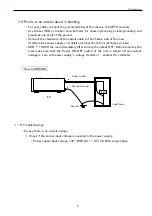
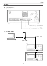
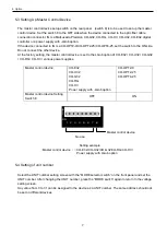
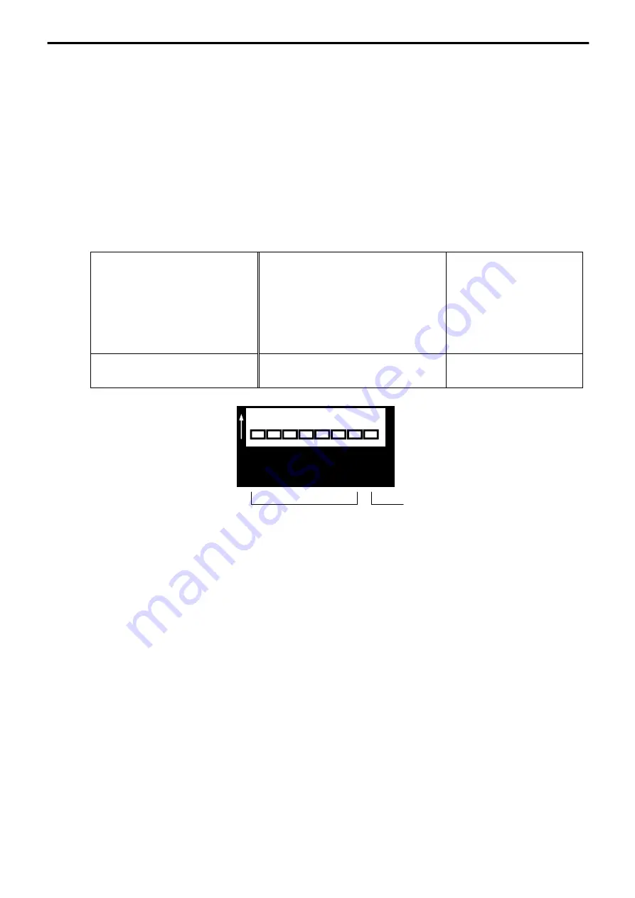
The master control device setup switch on the rear panel (switch 8) is to be used to set up the master
control device. Set the switch 8 to the OFF side when the device connected to the optic fiber cable
connection connector IN is a Matsusada Precision CO-G32, CO-RG, CO-HV, CO-U32, CO-E32 digital
controller or a power supply with -LGob option.
If the device connected to IN is a CO-OPT2-9/CO-OPT2-25/CO-OPT4-25, set the switch to the ON side.
Do not connect the other device.
At the factory setting, the master control device is set to the LGob option of CO-E32 / CO-U32 / CO-G32
/ CO-RG / CO-HV / various power supplies.
Master control device
CO-E32
CO-U32
CO-G32
CO-RG
CO-HV
Power supply with -LGob option
CO-OPT2-9
CO-OPT2-25
CO-OPT4-25
Master control device Setting
Switch 8
OFF
ON
5-4 Setting of unit number
Select the UNIT number sett
ing screen with the “MODE selector switch” on the front panel and set the
UNIT number. After changing the UNIT number, press the “MODE switch” again to return to the voltage
setting screen.
Any value from 0 to 31 can be assigned to the device as a UNIT number. The same address should not
be set on different devices.
5. Option
Setting example
・
Master control device
・・・
CO-E32/CO-U32/CO-G32/CO-RG/CO-HV/
Power supply with LGob option
No use
Master control device
ON
1
2
3
4
5
6
7
8
Summary of Contents for EP Series
Page 1: ...Rev 0 2 B N 035 9 114 035 9 114 MODEL EP series Instruction Manual ...
Page 19: ......
Page 20: ......

