
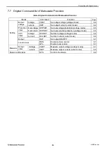
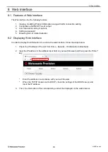


8 Web Interface
72
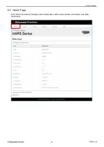
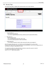
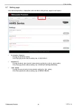
HARS series
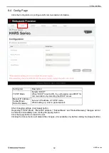
8-4 Config Page
Click the Config button to configure LAN communication information.
Setting item
Description
TCP/IP Mode
Selects “DHCP”.
When “DHCP” is set to ON, the unit usually uses DHCP for
communications by detecting the DHCP server.
Manual IP Address
Subnet Mask
Default Gateway
Set each IP address in TCP/IP mode.
When setting up, enter a period as well.
After changing settings, click [Apply] button.
Regarding "TCP/IP Mode", "Manual IP Address", "Subnet Mask", and "Default Gateway" changes will not
be reflected immediately even clicking the [Apply] button.
Click the Apply button to restart the unit.
Clicking the Cancel button will discard the changes. (It is available only before clicking the [Apply] button.)
Summary of Contents for HARS Series
Page 1: ...Instruction Manual F RA 001 3R3 MODEL HARS series B N 277 9 002 277 9 002 Rev 0 1 ...
Page 10: ......
Page 19: ...2 Before Using This Product 9 HARS series 2 6 3 Dimensions a Models 500W 1kW 60kV or lower ...
Page 20: ...2 Before Using This Product 10 HARS series b Models 500W 1kW 100kV 120kV ...
Page 21: ...2 Before Using This Product 11 HARS series c Models 2kW 3kW 60kV or lower ...
Page 22: ...2 Before Using This Product 12 HARS series d Models 2kW 3kW 100kV 120kV ...
Page 92: ......


