2 Installation and Operation
2-14
2-6 On the Occasion of Connection
In order to achieve high performance, high stability and low ripple of RE Series, it is important to
make sufficient preparation in advance for installation such as correct connection or grounding.
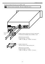
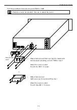
Be sure to attach the output terminal cover for ensuring safety (see 2-6-4 and 2-6-5 on the
following page).
2-6-1 Connecting Loads
・
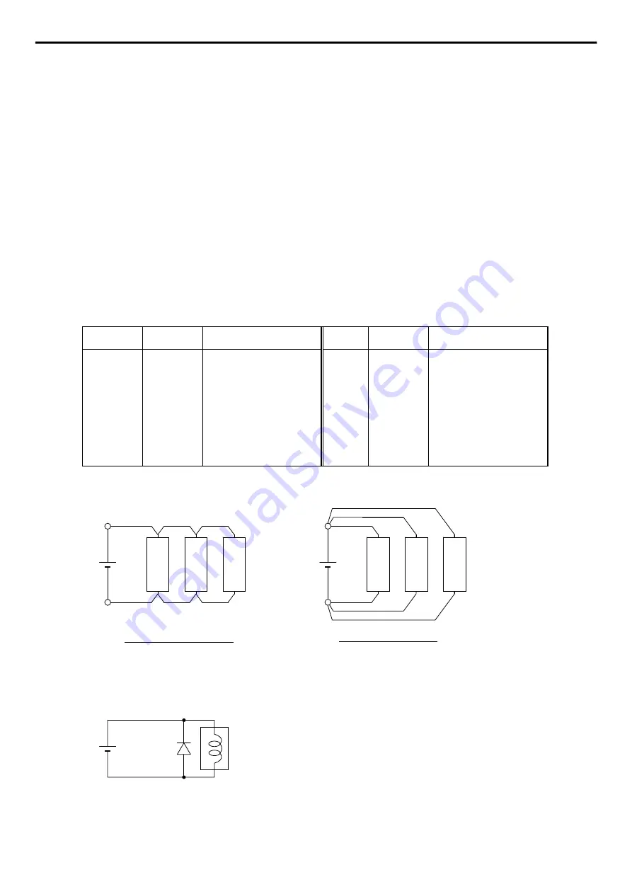
Use leads of sufficient thickness and make them as short as possible.
・
Use PVC cable that has enough resistance to the voltage used (resistant to 105 deg.C).
Wiring to loads requires taking into consideration the current capacity of the wire and the
limitation to the length of output wire of remote sensing (0.5 V/lead). Find the proper
thickness of wire in accordance with the following table.
AWG
mm
2
Maximum current(A)
AWG
mm
2
Maximum current(A)
18
16
14
12
10
8
7
0.8
1.3
2.1
3.3
5.3
8.4
10.6
2
7
11
18
23
39
53
6
4
2
1
1/0
2/0
3/0
13
21
33
42
53
67
85
67
106
170
209
270
330
350
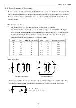
Parallel connection
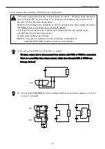
When using a dielectric load, insert a diode whose output voltage and current is higher than
those of the power supply to protect the power supply from the kickback of the load.
Lo
a
d
1
Lo
a
d
2
Lo
a
d
3
P.S
Improper connection
Lo
a
d
1
Lo
a
d
2
Lo
a
d
3
Proper connection
P.S
P.S
Di
Dielectric load
(Transformer, motor, etc.)


