Arrow Mark
51
10
52
53
White Mark
17
RIGHT SIDE
White Mark
LEFT SIDE
Arrow Mark
51
10
48
53
17
1
a.
b.
51
TOOL
78
10
52
53
17
A.
B.
C.
8
Assembly Instructions
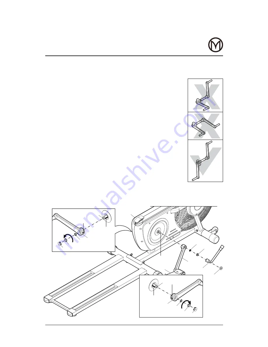
STEP 5
When attaching cranks ensure pedal arm rollers (113) run in
grooves on rear base (14).
a. Align arrow mark on crank to white mark on right axle secure
crank (10) with washer (53) and flange nut (52), tighten with
socket wrench & fit cap (51) to crank (10).
The right flange nut (52), black colour, has right hand thread and
is tightened by turning clockwise.
b. Align arrow mark on crank to white mark on left axle secure
crank (10) with washer (53) and flange nut (48), tighten with
socket wrench & attach cap (51) to crank (10).
The left flange nut (48), brass colour, has a left hand thread and
is tightened by turning anti-clockwise.
Important note
• It is possible to assemble the cranks (10) in the wrong
position as shown in inset drawings A and B. Once
assembled they will require a special tool (not provided) to
remove. Read & understand the assembly instructions before
attaching.
Important:
Flange nut on left side only
tightens anti-clockwise.
Summary of Contents for Air Elliptical With Bluetooth
Page 1: ...Air Elliptical With Bluetooth...
Page 22: ...20 Exploded Diagram...


