MAULE AEROSPACE TECHNOLOGY, INC.
MAINTENANCE MANUAL
FOR
M-8-235
Rev. B
30/41
A. DISASSEMBLY
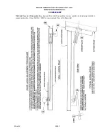
1. Remove cap (74B) - may be pried off with flat side of a screwdriver.
2. Hold the fork (69B) and loosen the nut (A1).
3. With the nut removed, carefully remove the fork spindle from the rest of the assembly.
Slowly rotate the fork back and forth while withdrawing it and collect the loose parts.
4. Clean all of the metal parts in solvent. Inspect all parts and replace any parts that ex-
hibit excessive wear.
B. SHIM SELECTION
1. Position the bearings (A5) in bracket (71B) and slide the fork (69B) through the bear-
ings. Do not install any of the other parts at this time.
2. Slide lock ring (73B) over the threaded end of the fork spindle and run nut (A1) down
until it bottoms on the lock ring.
3. Tighten the nut moderately and note whether or not there is any end play in the bear-
ings. If there is no endplay and no excessive rotational drag, shimming will not be re-
quired. If there is any bearing endplay, remove the nut and spindle and install one (1)
shim (83B) on the spindle and repeat the check. Normally only one (1) or two (2)
shims will be required to remove any bearing clearance. Too many shims will cause
the bearings to drag when the nut is tightened.
C. ASSEMBLY
1. Grease pack roller bearings (A5) and lock pin (13AB) with wheel bearing grease.
Grease the parts adjacent to lock pin. Do Not grease friction washer (72B-4) or the
parts adjacent to it.
2. Place the roller bearings (A5) in their races, the felt seals (78B-2) on the bearings, and
the three (3) springs (76B) in the three deeper holes in bracket (71B). Place friction
ring assembly (72B-3) over the springs with the pin in the shallow hole in bracket (71B).
Grease may be used to hold the foregoing parts in place. Do Not allow any grease on
the friction washer surface of the friction ring assembly (72B-3).
3. Place shim(s) (83B) on lower shoulder of the spindle on fork (69B). Place the friction
washer (72B-4) on the large diameter friction surface of the fork.
4. Carefully slide the fork spindle through the friction ring and bearings until the friction
washer is bottomed against the springs. Make sure that all parts stay in place.
5. Assemble lock ring (73B), arm (6) (with lock pin (13AB) and spring (14) installed),
shield (36), and pins (60AB) together as a unit. Make sure that the key end of lock pin
13AB) is properly aligned with the slot in lock ring (73B).


