background image

MAULE AEROSPACE TECHNOLOGY, INC. 

MAINTENANCE MANUAL 

FOR 

M-4-180V


Rev. A 
4/13/16


SECTION II


GENERAL MAINTENANCE


CLEANING AND CARE OF AIRCRAFT 


Keeping the performance, speed and durability that was built into your aircraft at the 

factory requires more than casual attention.  The accumulation of dirt and oil on the outside 
and debris inside does affect these factors and can be a fire hazard as well.  The first step to 
proper maintenance is a clean aircraft. 


EXTERIOR 


Frequent washing is good for your aircraft finish, especially during the first few 

months.  Use any car soap or detergent with a soft cloth or sponge and plenty of clean water.  
Drying should be done with a chamois.  Accumulation of oil, grease and exhaust carbon 
deposits should be removed frequently by using a soft cloth soaked in mineral spirits or other 
neutral cleaner. 


For general polishing, apply a good quality car polish or wax according to instructions.  

Clean Plexiglas with plenty of soap and water using grit free soft cloth, chamois or sponge.  
Use of a dry cloth on Plexiglas will not only cause scratches but will also build up an 
electrostatic field which will attract dust to the surface.  Blotting with a clean damp chamois 
will remove the charge and the dust.  After cleaning, polishing with a good Plexiglas cleaning 
product such as "Mirror Glaz" will keep the glass clean and help polish out minor scratches. 
 
INTERIOR 


Floorboards should be vacuumed frequently and can be cleaned with any good rug 

cleaner. 


Care should be taken in the disposal of candy wrappers, paper scraps, cigarette 

butts, etc.  These can work their way under the floorboards and become a fire hazard and 
moisture trap. 
 

NOTE: While washing the aircraft, ascertain that all drain holes are open.  Clean out 

any debris blocking them.  Accumulated water can be dangerous, so check behind the 
baggage compartment frequently. 


Textile upholstery may be cleaned using a vacuum cleaner.  Grease and oil spots on 

the upholstery should be treated with a spot remover or dry cleaning fluid.  Do not use soap 
and water on textile materials. 


Vinyl upholstery may be cleaned using soft whisk broom or suds of any mild soap 

(castile or olive oil base) in lukewarm water.  Use water sparingly as the upholstery otherwise 
requires a long time to dry if water trickles through the seam stitches. 
 

Summary of Contents for Vintage M-4-180V

Page 1: ...OR MAULE M 4 180V Vintage Rocket P N TLC M 4 180V PERFORMANCE THAT COUNTS Rev A 04 13 16 2099 Georgia Hwy 133 South Moultrie GA 31788 PC SMM Tel 229 985 2045 Fax 229 890 2402 985 2048 www mauleairinc com ...

Page 2: ...hin one 1 year after delivery of such airplane to the original purchaser be returned to Maule with transportation charges prepaid and which upon Maule s examination shall disclose to its satisfaction to have been thus defective this warranty being expressly in lieu of all other warranties expressed or implied and all other obligations or liabilities on the part of Maule and Maule neither assumes n...

Page 3: ...nd Care of Aircraft 7 Inspection Guides 9 Weighing Procedure 14 Rigging Procedures 16 Lubrication 18 Towing 18 Fabric Repairs 19 SECTION III MAJOR COMPONENT PARTS Wings 20 Lift Struts 20 Fuselage 20 Movable Surfaces and Controls 21 Landing Gear Wheels and Brakes 22 SFS P8B Tailwheel 25 Figure One 27 Power Plant System 28 Fuel System 30 Electrical System 30 Electrical Schematic 14V 31 Electrical Sc...

Page 4: ...MAULE AEROSPACE TECHNOLOGY INC MAINTENANCE MANUAL FOR M 4 180V 4 Rev A 4 13 16 LOG OF REVISIONS REV TO PAGES DESCRIPTION DATE A 6 17 21 22 Changed oleo strut oil to API GL 4 or GL 5 gear oil 04 13 16 ...

Page 5: ...etic fabric Front doors on right and left sides Landing Gear Main gear split axle type spring oil oleo shock absorber Hydraulic Brakes Steerable tailwheel Control Systems Dual controls wheels and rudder pedals All controls directly cable driven Fuel control shut off valve is at the left lower side panel Mechanical flap and trim controls are at the center on the floor All other controls switches et...

Page 6: ... Elevator Trim tab 1 1 sq ft i Rudder Tab 38 sq ft FLUID CAPACITIES AND SPECIFICATIONS a Main Fuel Tanks Inboard 100 Octane Right Main Tank 21 5 gallons Left Main Tank 21 5 gallons Note 2 3 gallons unusable fuel per 21 5 gallon main tank b Auxiliary Fuel Tanks Outboard 100 Octane Right Auxiliary Tank 11 5 gallons Left Auxiliary Tank 11 5 gallons c Engine Oil SAE 50 above 60 F SAE 40 at 30 to 90 F ...

Page 7: ...l not only cause scratches but will also build up an electrostatic field which will attract dust to the surface Blotting with a clean damp chamois will remove the charge and the dust After cleaning polishing with a good Plexiglas cleaning product such as Mirror Glaz will keep the glass clean and help polish out minor scratches INTERIOR Floorboards should be vacuumed frequently and can be cleaned w...

Page 8: ...emoved with turpentine However such cleaning agents are liable to affect the dust repellent finish of the vinyl if used in excess of the actual requirements Never use volatile solvents such as lacquer thinner acetone etc on upholstery The cleaning should be completed by wiping the surface of the vinyl dry with a clean cloth particularly in the seam No attempt should be made to apply preservatives ...

Page 9: ... tubes for cracks Inspect muffs for cracks before reinstalling 4 Inspect gascolator clean if necessary 5 Inspect engine controls for security and proper operation 6 Clean or replace air filter See page 29 for Brackett air filter 7 Inspect all engine and engine mount attach bolts 8 Inspect all engine fuel and oil lines for general condition and security 9 Check all engine compartment electrical con...

Page 10: ...rity and cracking 5 Clean gascolator screen 6 Retorque bolts attaching engine mount to fuselage engine to engine mount Visually inspect mount structure for condition See Engine Mount under Power Plant System 7 Inspect induction system and air box for cracks and security Check rubber seal on air valve for condition CAUTION Use rubber seal with cotton insert only when replacing seal B AIRCRAFT 1 Rem...

Page 11: ...brake pad for wear cuts chafing leaks and general condition Repack wheel bearings See page 12 for jacking information 9 Remove landing gear top fairings and inspect attaching fittings and bolts for security corrosion and cracks and inspect brake hose for security chafing and leaks 10 Check resilience of oleo springs A lax spring is indicated by a low wing condition when the airplane is on the grou...

Page 12: ...MAULE AEROSPACE TECHNOLOGY INC MAINTENANCE MANUAL FOR M 4 180V 12 Rev A 4 13 16 ...

Page 13: ...ood preservative such as Black Bear Paralketone Preventative Black Bear Co Long Island City NY Preferred LPS 3 Heavy Duty Rust Inhibitor LPS Laboratories Inc Tucker GA NOTE Larger stainless steel turnbuckles and corrosion resistant steel fasteners for the elevator cables are approved and recommended for airplanes operating in a potentially corrosive environment 15 Lubricate all chains and points o...

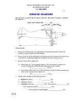
Page 14: ...until the aircraft is level 3 Measure the following distances a Wheel base L the horizontal distance from the tailwheel weight point center of axle to the main wheel weight point center of axle L __________________ Inches b Main Wheel Station D the horizontal distance from the main wheel weight point center of axle to the datum line D __________________ Inches 4 Measure the weights at the followin...

Page 15: ...weight C G and moment a Center of Gravity inches L x T D W i e C G _____________ ____________ ___________inches b Moment inch pounds W x C G i e Moment _____________ x ____________ ___________inch lbs CENTER OF GRAVITY LIMITS 15 6 to 19 0 2300 lbs 11 0 to 19 0 1500 lbs or less RIGGING PROCEDURES 1 LEVELING Laterally Using a level twenty four 24 inches long place across the front spar carry through...

Page 16: ...e protractor chordwise just inboard of the wing tip and adjust the rear strut to give trailing edge up difference from the wing root angle 4 TAIL ASSEMBLY With the airplane in level position the stabilizers should be leveled at their rear spars The hinge line should be straight from tip to tip The vertical stabilizer should be plumb at the hinge 5 AILERONS Adjust the ailerons to streamline positio...

Page 17: ... rudder when the aileron and rudder controls are centered The tab may be used to adjust rudder trim In normal cruise it is desirable to have the ball centered with the Rudder Trim control out to first line This allows for inflight adjustment of rudder trim in cruise Rudder trim may be adjusted by changing the position of the tab cables located just over the front doors on the inside of the airplan...

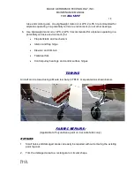
Page 18: ...ating in a potentially corrosive environment for Flap bellcrank and mechanism Aileron and flap hinge Elevator and trim tab Tailwheel fork Control pulley bearings and control surface hinges TOWING Aircraft can be towed using a Maule tow bar p n TB101 or equivalent as shown below FABRIC REPAIRS Applicable to Polyurethane paint on Ceconite fabric only REPAIRS 1 Small holes and damaged areas can easil...

Page 19: ...pply a second coat of the thinned urethane adhesive and lay the patch in the wet bed of adhesive smoothing the edges while applying a topcoat of the thinned urethane adhesive working he edges down Allow to dry at least 8 hours prior to any shrinkage SHRINKING THE REPAIR AREA When using an iron to shrink the patch always use a piece of aluminum foil over the area to be tautened and the surrounding ...

Page 20: ...tructural parts are made of cold rolled steel 1008 to 1015 If it becomes necessary to replace any fuselage members sleeve type splices should be made in accordance with practices outlined in FAA AC 43 13 1 Aircraft Inspection and Repair The forward fuselage section is aluminum covered 5052 H34 or 2024 T3 The firewall and bottom fuselage just aft of the cooling air egress are made of 018 galvanized...

Page 21: ...ould be made to check cotter pins lock nuts and to see if they have been damaged in any way RUDDER The rudder structure is very similar to the elevators No maintenance other than inspection for corrosion is needed The hinges should be cleaned and lubricated with light engine oil at frequent intervals The cable attachment points should be checked for wear and corrosion TRIM AND RUDDER TABS These su...

Page 22: ...allowing excess oil to escape 4 Install cylinder head bolts filler plug and safety Torque bolts to 100 140 in lb 5 Reinstall strut on airplane being careful to get the spacers in at the top attaching bolt 6 Work airplane up and down on strut and check for oil leaks LANDING GEAR LEGS AND AXLE The landing gear is made of chrome molybdenum steel 4130 and has an aluminum skin 2024 T3 These need no mai...

Page 23: ...ire Rotate axle nut CW or CCW to align nearest axle nut hole with axle slot Insert axle nut retainer spring fully into axle slot and ensure engagement with holes in axle nut 14 Inflate tire to 35 psi to seat tire on rims and back off to 27 34 psi normal pressure 16 18 psi for oversize tires 15 Thoroughly inspect landing gear and axle check that axle attach bolts are torqued to 90 in lb dry 16 Insp...

Page 24: ...e bleeder valve open which will force fluid into the receptacle where a check can be made for escaping air bubbles Continue to actuate pedal until no more air bubbles are observed 5 When no bubbles are observed close the bleeder valve after pedal has returned to off position Remove the plastic tube 6 Recheck reservoir level and fill as necessary ...

Page 25: ...ntervals and keep reservoir full at all times 5 Vent plug stopped up 5 If vent hole in reservoir plug becomes stopped there is a possibility that a partial vacuum will be created in the system which will interrupt the fluid flow in the system Clear vent hole 6 Improper bleeding air mixed with fluid 6 Bleed brakes 7 Master cylinder cup or O ring wear 7 Replace brake cylinder cups and O rings DRAGGI...

Page 26: ...parts and replace any parts that exhibit excessive wear B SHIM SELECTION 1 Position the bearings A5 in bracket 71B and slide the fork 69B through the bearings Do not install any of the other parts at this time 2 Slide lock ring 73B over the threaded end of the fork spindle and run nut A1 down until it bottoms on the lock ring 3 Tighten the nut moderately and note whether or not there is any end pl...

Page 27: ...til the friction washer is bottomed against the springs Make sure that all parts stay in place 5 Assemble lock ring 73B arm 6 with lock pin 13AB and spring 14 installed shield 36 and pins 60AB together as a unit Make sure that the key end of lock pin 13AB is properly aligned with the slot in lock ring 73B 6 Slide the lock pin subassembly over the threaded end of the fork spindle being careful to k...

Page 28: ...FIGURE 1 D TAILWHEEL INSTALLATION 1 Check all bolts and nuts holding the tail springs to the fuselage They must be tight so that there is no play or side movement in the springs or their attachment 2 Tighten the bracket bolt and back off enough to install the cotter pin There must ...

Page 29: ...e firewall to the fuselage structure by means of four 4 3 8 attaching bolts requiring a torque of 13 3 15 8 ft lb which should be checked for tightness periodically An extremely close visual inspection of the engine mount should be made to periodically check for cracks dents weld failures etc of the mount tubular members as well as the general condition of the mount At regular intervals the attach...

Page 30: ...termined by environmental conditions encountered Replace when cleaning no longer services unit EXHAUST SYSTEM Remove Heater Shells check mufflers and tailpipes for cracks Check attachments for security Note that the tailpipe clamps and the muffler to header attachments should not be tightened to the point of rigidity but should be loose enough to be moved easily by hand Check the heater shell reta...

Page 31: ...t cruise rpm Paragraph 4 26 d of FAA AC 43 13 1A limits the total continuous load to 80 of the total rated capacity or 50 amperes A 50 amp circuit breaker is installed in aircraft BATTERY A lead plate type storage battery rated at 12 or 24 volts is installed in the battery frame assembly under the copilot s seat or on firewall The battery supplies current for the airplane electrical system when th...

Page 32: ...ENANCE MANUAL FOR M 4 180V 32 Rev A 4 13 16 Electrical Schematic The wire numbering system has been designed to ease tracing a faulty wire The circuit tracing code is as shown below in the schematic Wires are plainly labeled near each end ...

Page 33: ...ENANCE MANUAL FOR M 4 180V 33 Rev A 4 13 16 Electrical Schematic The wire numbering system has been designed to ease tracing a faulty wire The circuit tracing code is as shown below in the schematic Wires are plainly labeled near each end ...

Page 34: ...MAULE AEROSPACE TECHNOLOGY INC MAINTENANCE MANUAL FOR M 4 180V 34 Rev A 4 13 16 ...

Page 35: ... Regulations unless an alternate program has been FAA approved The airframe does not have mandatory life limits or overhaul requirements See Textron Lycoming Operator s Manual p n 60297 12 Revision No 60297 12 6 or later and the Hartzell Owner s Manual and Logbook p n 115N Revision 10 or later for the constant speed prop or the Sensenich Fixed Pitch Metal Propellers Instructions For Use and Care d...

Reviews: