50
DS508UM1
2.17
Timer Counters
Two identical timer counters are integrated into the EP7312. These are referred to as TC1 and TC2. Each
timer counter has an associated 16-bit read / write data register and some control bits in the system control
register. Each counter is loaded with the value written to the data register immediately. This value will then
be decremented on the second active clock edge to arrive after the write (i.e., after the first complete period
of the clock). When the timer counter under flows (i.e., reaches 0), it will assert its appropriate interrupt.
The timer counters can be read at any time. The clock source and mode are selectable by writing to various
bits in the system control register. When run from the internal PLL, 512 kHz and 2 kHz rates are provided.
When using the 13 MHz external source, the default frequencies will be 541 kHz and 2.115 kHz, respec-
tively. However, only in non-PLL mode, an optional divide by 26 frequency can be generated (thus gener-
ating a 500 kHz frequency when using the 13 MHz source). This divider is enabled by setting the OSTB
(Operating System Timing Bit) in the SYSCON2 register (bit 12). When this bit is set high to select the
500 kHz mode, the 500 kHz frequency is routed to the timers instead of the 541 kHz clock. This does not
affect the frequencies derived for any of the other internal peripherals.
The timer counters can operate in two modes: free running or pre-scale.
2.17.1
Free Running Mode
In the free running mode, the counter will wrap around to 0xFFFF when it under flows and it will continue
to count down. Any value written to TC1 or TC2 will be decremented on the second edge of the selected
clock.
2.17.2
Prescale Mode
In the prescale mode, the value written to TC1 or TC2 is automatically re-loaded when the counter under
flows. Any value written to TC1 or TC2 will be decremented on the second edge of the selected clock. This
mode can be used to produce a programmable frequency to drive the buzzer (i.e., with TC1) or generate a
periodic interrupt. The formula is F=(500 kHz) / (n+1).
2.18
Real Time Clock
The EP7312 contains a 32-bit Real Time Clock (RTC). This can be written to and read from in the same
way as the timer counters, but it is 32 bits wide. The RTC is always clocked at 1 Hz, generated from the
32.768 kHz oscillator. It also contains a 32-bit output match register, this can be programmed to generate
an interrupt when the time in the RTC matches a specific time written to this register. The RTC can only
be reset by an nPOR cold reset. Because the RTC data register is updated from the 1 Hz clock derived from
the 32 kHz source, which is asynchronous to the main memory system clock, the data register should al-
ways be read twice to ensure a valid and stable reading. This also applies when reading back the RTCDIV
field of the SYSCON1 register, which reflects the status of the six LSBs of the RTC counter.
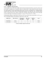
Summary of Contents for EP7312
Page 8: ...DS508UM1 9 Part I EP7312 User s Manual...
Page 58: ...DS508UM1 59 Part II Pin and Register Reference...
Page 122: ......


