DS508UM1
73
6.1.3
PDDR — Port D Data Register
ADDRESS: 0x8000.0003
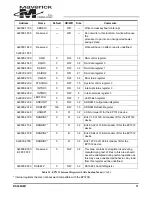
Values written to this 8-bit read / write register will be output on Port D pins if the corresponding data
direction bits are set low (port output). Values read from this register reflect the external state of Port
registers in the EP7312 are reset (cleared to zero) by a system reset (i.e., nPOR, nURESET, or nP-
WRFL signals becoming active), except for the SDRAM refresh period register (SDRFPR), the Real
Time Clock data register (RTCDR), and the match register (RTCMR), which are only reset by nPOR
becoming active. This ensures that the SDRAM contents and system time are preserved through a
user reset or power fail condition.
Note:
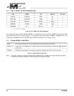
The following Register Descriptions refer to Little Endian Mode Only
6.1.4
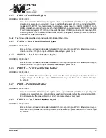
PADDR — Port A Data Direction Register
ADDRESS: 0x8000.0040
Bits set in this 8-bit read / write register will select the corresponding pin in Port A to become an output,
clearing a bit sets the pin to input. All bits are cleared by a system reset.
6.1.5
PBDDR — Port B Data Direction Register
ADDRESS: 0x8000.0041
Bits set in this 8-bit read / write register will select the corresponding pin in Port B to become an output,
clearing a bit sets the pin to input. All bits are cleared by a system reset.
6.1.6
PDDDR — Port D Data Direction Register
ADDRESS: 0x8000.0043
Bits cleared in this 8-bit read / write register will select the corresponding pin in Port D to become an
output, setting a bit sets the pin to input. All bits are cleared by a system reset so that Port D is output
by default.
6.1.7
PEDR — Port E Data Register
ADDRESS: 0x8000.0080
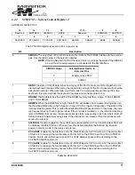
Values written to this 3-bit read / write register will be output on Port E pins if the corresponding data
direction bits are set high (port output). Values read from this register reflect the external state of Port
E, not necessarily the value written to it. All bits are cleared by a system reset.
6.1.8
PEDDR — Port E Data Direction Register
ADDRESS: 0x8000.00C0
Bits set in this 3-bit read / write register will select the corresponding pin in Port E to become an output,
while the clearing bit sets the pin to input. All bits are cleared by a system reset so that Port E is input
by default.
Summary of Contents for EP7312
Page 8: ...DS508UM1 9 Part I EP7312 User s Manual...
Page 58: ...DS508UM1 59 Part II Pin and Register Reference...
Page 122: ......

