7
© Copyright Century UK Limited 2012 www.centuryuk.com
4. Fuselage
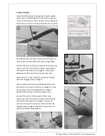
Slide the horizontal tail plane into the fuselage
slot as shown, (image 18). Make certain the tail
plane is centred correctly. Connect the remaining
elevator servo to its horn and fix the cover as
described in Section 2.
Locate the “Y” lead marked “2” and connect to
the two elevator servos. Route the remaining plug
through the fuselage toward the wing area.
Locate the “Y” lead marked “4” and connect one
leg to the tail-wheel steering servo. Locate the
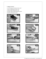
extension lead marked “5” and connect to the
retracting tail wheel unit, (image 19). Route the
other end of this lead through the fuselage
towards the wing area.
Secure the retracting tail wheel unit in position
using the four M3 x 10mm self-tapping screws,
(image 20).
Centre the tail wheel steering servo and fit the
control horn in position. Electrically lower the
retracting tail wheel to ensure the plastic control
horn locates correctly with the control pin in the
servo horn, (image 21).
The remaining connector from the “Y” lead
marked “4” should now be connected to the
rudder servo, (image 22).
Slide the vertical fin and rudder assembly into
position on the fuselage. Make certain the rudder
servo wire is routed neatly. Secure the assembly
in position using the two M3 x 75mm screws,
(image 23.)
M3 x 10mm (x4)
(x1)
M3 x 75mm (x2)
18
19
20
21
22
23


