background image

16

5. OPERATING INSTRUC-

TIONS

1. How to mount / remove the Bat-

tery pack

Before mounting / removing the Battery 
pack from the tool, set the Rotational di-
rection switch(Fig. B.11) at middle position, 
and keep hands away from the Trigger 
switch(Fig. B.12).

Before operation, make sure to check the 
Battery pack is securely set in the tool.

Failure to do so may cause serious injury.

1

(Fig. N) When mounting the Battery pack, 
insert the Battery pack in the tool so that 
the rails of the Battery and the tool fit 
each other. Slide the Battery pack to the 
end, until the click is heard. The Latch-
es(Fig. N 16) must be returned to the orig-
inal position.

2

(Fig. F) When removing the Battery pack, 
remove it from the tool by pushing on its 
latches (Fig. F 16) from both sides while 
firmly holding the grip of the tool.

2. How to operate the Trigger switch 

(continuously variable)

(Fig. O) To start the tool, pull the Trigger switch 
(continuously variable). Release the Trigger 
switch to stop.
The Trigger switch is continuously variable, 
which makes the tool speed increased by in-
creasing pressure on the Trigger switch (vice 
versa).

When pulling or releasing the Trigger, the 
LED lamp on the Control panel (Fig. B 10) 
flashes (Orange) for a moment. This shows 
the power is on.

3. How to operate the Changeover 

switch

(Fig. P and Q) Seeing the tool as shown in the 
figure P, press the Changeover switch (Fig. P 
11) to the right to operate the tool clockwise. 
Press the switch to the left to operate the tool 
counterclockwise. Set the switch at the middle 
position to lock the tool's operation. When the 
tool is not in use, make sure to set the switch at 
middle position.

Do not operate the Changeover switch dur-
ing the tool is in operation. 

Operating the switch during the tool's opera-
tion may damage the tool.

4. How to use the Side handle and 

the Depth gauge

Make sure to operate the tool with holding 
the tool firmly with both hands, by the Side 
handle and the grip. 

Use only the original Side handle, which is 
included in the package.

Before attaching / removing the Side han-
dle or the Depth gauge, keep the fingers 
away from the Trigger switch, and remove 
the Battery pack from the tool.

When unable to attach the Side handle se-
curely, do not use the tool.

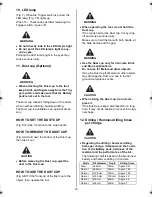
(Fig. R) The Side handle (Fig. R 3) is 360 deg. ro-
tatable. Adjust it at the best angle by loosening 
and tightening the handle

(Fig. S) The Depth gauge(Fig. S 1) enables ad-
justment of hammer-drilling depth. The Depth 
gauge is adjustable by loosening and tightening 
the Side handle (Fig. R 3)

The Depth gauge is for rough adjustment of the 
hammer-drilling depth. For precise depth adjust-
ment, measure the hammer-drilling depth with a 
measuring equipment.

WARNING

WARNING

CAUTION

WARNING

PJR265_CE.book  16 ページ  2010年10月13日 水曜日 午後4時51分

Summary of Contents for PJR265(CE)

Page 1: ...SHLESS ROTARY HAMMER ORIGINAL USER MANUAL Original instructions ENGLISH BEFORE USING THIS TOOL STUDY THIS MANUAL TO ENSURE SAFETY WARNING AND INSTRUCTIONS KEEP THESE INSTRUCTIONS WITH THE TOOL FOR FUT...

Page 2: ...2 1 4 5 11 12 25 10 9 8 7 6 3 2 Fig B 13 14 16 17 15 Fig C 24 23 22 21 20 19 18 Fig D 13 Fig E 16 1 2 Fig F...

Page 3: ...3 20 Fig G 7 Fig H 20 Fig I 20 Fig J Fig K Fig L 13 Fig M 16 Fig N...

Page 4: ...4 12 Fig O 11 Fig P Fig Q 3 1 Fig R 1 Fig S 2 Fig T 2 Fig U Fig V...

Page 5: ...5 5 4 Fig W 8 10 Fig X 6 12 Fig Y Fig Z Fig AA Fig AB...

Page 6: ...rac tions can cause you to lose control 2 ELECRRICAL SAFETY Power tool plugs must match the out let Never modify the plug in any way Do not use any adapter plugs with earthed grounded power tools Un m...

Page 7: ...nch before turning the power tool on A wrench or a key left attached to a rotat ing part of the power tool may result in a personal injury Do not overreach Keep proper footing and balance at all times...

Page 8: ...tional right power tools that are no longer usa ble must be collected separately and dis posed of in an environmentally correct manner DEFFECTIVE OR DEAD OUT BATTERY PACKS BATTERIES MUST BE RECY CLED...

Page 9: ...il and grease 7 LET THE TOOL WARM UP FOR SEV ERAL MINUTES BEFORE USE In cold weather or when the tool has not been used for a long period of time the in ternal lubrication in the tool might not be in...

Page 10: ...ontinual use of the Battery charger Rest the Charger for 15 minutes between charges to avoid functional trouble with the unit 13Any objects that block the ventilation holes or Battery pack receptacle...

Page 11: ...WER CORD 24 CE VDE POWER PLUG 2 TOOL SPECIFICATIONS Battery charger PRODUCT NO PJR265 WEIGHT 3 7kg 8 1lbs Battery included HEIGHT 210mm 8 1 4 WIDTH 82mm 3 1 4 LENGTH 332mm 13 1 16 TOOL HOLDER SDS PLUS...

Page 12: ...CE 4 APPLICATIONS Hammer drilling in the following materials Concrete Brick Stone Drilling in the following materials Wood Metal 5 ABOUT PRODUCTION YEAR This product bears production number in the bod...

Page 13: ...heck the charging re ceptacle If there are any foreign objects remove them with a soft dry cloth If the orange light still blinks or there are no foreign objects there may be a problem with the batter...

Page 14: ...0 minutes except at low temperatures SERVICE LIFE OF BATTERY PACK If any condition described below is observed the battery pack is at the end of its service life Re place it with a new one Although th...

Page 15: ...If the temperature of the battery pack is too high Battery recharging starts automatically when the tem perature drops below the limit If the temperature of the battery pack is too low Place the batte...

Page 16: ...to operate the Changeover switch Fig P and Q Seeing the tool as shown in the figure P press the Changeover switch Fig P 11 to the right to operate the tool clockwise Press the switch to the left to o...

Page 17: ...set the lever to the for drilling 1 Hold the tool firmly with both hands 2 Point the bit straight to the drilling object Do not apply excess pressure to the drill ing object Applying excess pressure m...

Page 18: ...ole 6 When hammer drilling in the thin object apply a plywood panel to the object in or der to prevent cracking the object 9 Slow mode When hammer drilling a small diameter smaller than 5mm hole in Co...

Page 19: ...rate the tool When operating the tool do not hold the Dust cup If the tool is held at the Dust cup it may drop off and cause serious injury Make sure to hold the tool with both hands at the Side handl...

Page 20: ...AGE Do not store the tool in a cold weather envi ron ment Keep the tool in a warm area When not in use the tool should be stored in a warm and dry place Keep out of reach of chil dren All quality tool...

Page 21: ...RTS LIST 19 16 12 35 34 33 32 29 28 27 10 11 9 23 21 24 25 A 1 2 7 3 4 5 6 A 31 26 C 17 55 51 49 53 54 65 C 8 18 22 30 54 66 56 64 67 20 43 36 37 39 41 40 42 38 B 44 50 46 47 48 B 45 56 57 52 58 59 60...

Page 22: ...ounter sunk screw 4 10 O ring as 568 028 oil seal 009 inner housing unit felt O ring Type 4 C P65 special plain washer 28 6X33X1 hex socket head cap srew M46X16 mec inner shaft unit conical coil sprin...

Page 23: ...J70073 PJ10907 EE39841 BB71328 CC42513 PJ10900 PJ10901 PJ10947 ball holder retainer front cap push button compression spring 9021 change lever unit SIDE HANDLE ASSY relay terminal special plain washer...

Page 24: ...ctives ci dessus en utilisant les standards Europ ens suivants Directive de M canique EN ISO 12100 1 2003 A1 2009 EN ISO 12100 2 2003 A1 2009 EN ISO 14121 1 2007 EN 60745 1 2009 EN 60745 2 2 2004 Dire...

Reviews: