4
DRIVING DEPTH ADJUSTMENT DIAL
Adjust the driving depth by twisting the adjustment dial
b
as in-
dicated below.
TRIGGER LOCK MECHANISM (Fig.13)
This tool has a Trigger Lock. The trigger should be locked at all
times until you intend to drive nail into the work surface. Push and
rotate the Trigger LOCK Dial
1
clockwise from LOCK to UN-
LOCK position immediately before driving nails. When fastening
is complete, push and rotate switch counterclockwise to LOCK
position.
CONTACT TIP (Fig.14) (HN90F, HN65)
Attach the Contact Tip
1
on the tip of Contact Arm
2
, when driv-
ing nails to a soft material.
The Contact Tip can be kept on the Arm Cover
3
when not using.
REMOVING JAMMED NAILS (Fig.15)
• ALWAYS disconnect the air supply.
• Wear gloves when removing jams; do not use bare hands
• Confirm that you have removed all nails from nose of tool
before reconnecting to air supply.
1
Disconnect the air supply.
2
Open the tool door and remove nails from inside of the mag-
azine.
3
Insert a thin metal stick in the tool nose and hit the metal
stick with a hammer or remove the jam with a flathead
screwdriver.
4
Put back the nails on the feed pawl and close the tool door.
WHEN USING THE TOOL FOR STEEL PLATES
(HN90F, HN65)
(HN65) This tool is exclusively designed for 1.6mm / 16Ga. to
2.3mm / 13Ga. thick light gauge steel.
(HN90F) This tool is exclusively designed for 1.6mm / 16Ga. to
3.2mm / 11Ga. thick light gauge steel.
When using it, comply with the Work Standards, considering the
object condition and work site environment.
1
Select appropriate nails according to the object thickness,
seeing the Nail Selection Criteria Chart.
∗
The nails may not be driven into the object depending on its
hardness or thickness.
∗
If the object is thicker than an appropriate range of thickness,
the nails may not be driven into it because of being bent.
2
If the thickness of the light gauge steel foundations material
used is 3.2mm / 11Ga., use the 2.9mm / .113" nails for steel
plate. (HN90F)
3
Never drive the nails directly into the light gauge steel be-
cause they will fly off, endangering you.
4
Be sure to apply the discharge outlet to the object at a right
angle. If applied obliquely, the nails will fly off, endangering
you.
5
Never use the nails for the roofs (roof foundations included)
or ceilings (ceiling foundations included).
6
If the nails are driven into the steel plate too deeply, their
holding force will be extremely reduced. When working with
the tool, fully check the driven conditions.
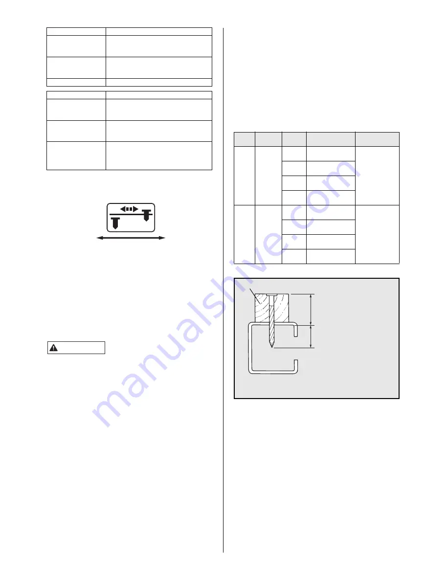
Nail Selection Criteria
REPLACING THE AIMING GUIDE LOCATOR
(HN65J)
The aiming guide locator is worn out depending on the frequency
of use.
If the machine cannot be easily held vertically when setting the
aiming guide locator in a hole in a metal fitting, it is about time to
replace.
Replace it in the following procedure:
1
(Fig.16) Remove a rubber washer
1
with a regular
screwdriver to pull out a pin
2
. Push the nail leg guide
3
to remove the aiming guide locator
4
.
2
(Fig.17) Attach a new aiming guide locator, set the pin and put
back the rubber washer.
When replacing the aiming guide locator, contact the nearest
MAX CO., LTD. authorized distributor.
CHANGING THE HOOK DIRECTION (HN90F)
(Fig.18) The hook can be directed in the two direction. Remove
the hexagon socket cap screw with hexagon wrench, change the
direction, and then, put back the bolt to reassemble.
PROCEDURE
1
Pulling the Trigger and keeping it
pulled.
2
Depressing the Contact Arm.
CONTACT TRIP WITH
ANTI-DOUBLE FIRE
MECHANISM
The tool fires a nail each time when the
Contact Arm is depressed.
SEQUENTIAL TRIP
The tool cannot fire a nail.
PROCEDURE
1
Depressing the Contact Arm.
2
Pulling the Trigger and keeping it
pulled.
CONTACT TRIP WITH
ANTI-DOUBLE FIRE
MECHANISM
The tool fires a nail.
The tool cannot fire a second nail until
the Trigger is released.
SEQUENTIAL TRIP
The tool fires a nail.
In order to fire a second nail, you should
both release the Trigger and remove the
Contact arm from the surface.
Deep
Shallow
WARNING
Tool Diameter Length
Object thickness
(Total) range
Light gauge
steel thickness
HN65
HN90F
2.5mm
(.098")
45mm
(1-3/4")
25 to 35mm
(1" to 1-3/8")
1.6 to 2.3mm
(16Ga. to
13Ga.)
50mm
(2")
30 to 40mm
(1-1/8" to 1-1/2")
57mm
(2-1/4")
35 to 45mm
(1-3/8" to 1-3/4")
65mm
(2-1/2")
45 to 55mm
(1-1/2" to 1-1/8")
HN90F
2.9mm
(.113")
45mm
(1-3/4")
25 to 35mm
(1" to 1-3/8")
1.6 to 3.2mm
(16Ga. to
11Ga.)
50mm
(2")
30 to 40mm
(1-1/8" to 1-1/2")
57mm
(2-1/4")
35 to 45mm
(1-3/8" to 1-3/4")
65mm
(2-1/2")
45 to 55mm
(1-1/2" to 1-1/8")
Wood
Object thickness
(Total) range
Penetration amount
Light gauge steel:
(HN65) 1.6mm (16Ga.) to 2.3mm
(13Ga.) thick
(HN90F) 1.6mm (16Ga.) to 3.2mm
(11Ga.) thick
∗
For the 3.2mm (11Ga.) thick light gauge steel, use the
2.9mm (.113") nails for steel plates. (HN90F)
All manuals and user guides at all-guides.com