i-32V5H MIDI
Chiller and Inverter Air/Water heat pumps with axial fan
15
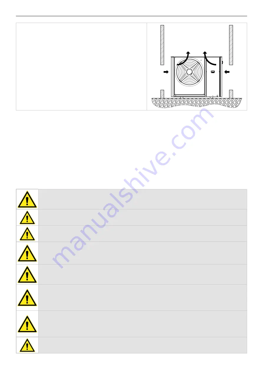
In the case of winds with speeds in excess of 13.9-17.1 m/s (strong winds ac
-
cording to the Beaufort scale), the use of windbreaks is recommended.
It is always advisable to make an environmental impact assessment based on the power and sound pressure data given in the technical data
chapter and the sound emission limits based on the installation area of the unit, with reference to the DPCM of 14/11/1997. An assessment must
also be made if the unit is installed in the vicinity of workers, according to D. LGS. 81/2008 Art. 189 and following.
3.3
HYDRAULIC CIRCUIT
The hydraulic connections must be made in accordance with national or local regulations; the piping can be made of steel, galvanised steel or
PVC. The pipes must be carefully sized according to the nominal water flow rate of the unit and the pressure drops of the hydraulic circuit. All
hydraulic connections must be insulated using closed-cell material of adequate thickness. The chiller must be connected to the piping using new,
non-reused flexible couplings. It is recommended to install the following components in the hydraulic circuit:
•
Thermometers to measure the temperature in the circuit
•
Manual gate valves to isolate the chiller from the hydraulic circuit.
•
Y-shaped metal filter and a dirt separator (installed on the return pipe from the system) with a metal mesh of no more than 1 mm (obligatory
to maintain the validity of the guarantee).
•
Charging unit and discharge valve where necessary
CAUTION: When dimensioning the pipes, make sure that the maximum system-side leakage is not exceeded as shown in the
technical data table (see useful head).
CAUTION: connect the pipes to the connections, always using the key-to-wrench system.
CAUTION: create a suitabe outlet for the safety valve.
CAUTION: The expansion tank, to be provided externally, must be suitably sized according to the type and volume of fluid,
the variation of temperatures and pressures in the system.
CAUTION: The return line from the system must be at the "WATER INPUT" label, otherwise the evaporator could freeze.
CAUTION: It is obligatory to install a metal filter (with a mesh size of no more than 1 mm) and a dirt separator on the return
pipe from the installation labelled "WATER INPUT". If the flow switch is tampered with or altered, or if the metal filter and
dirt separator are not present on the installation, the warranty will be immediately void. The filter and the dirt separator
must be kept clean, so make sure they are still clean after the unit is installed and check them periodically.
All units leave the factory with a flow switch (factory installed). If the flow switch is tampered with or removed, or if the wa
-
ter filter and deflector are not present in the unit, the guarantee will be invalid. Refer to the wiring diagram enclosed with
the unit for the connection of the flow switch. Never connect the flow switch connections in the terminal block.
The heating system and safety valves must comply with the requirements of EN 12828


