ADVANTIX
SPA
Via
Mansoldo
Gettuglio
–
Loc.
La
Macia
Z.A.I
–
37040
ARCOLE
(Verona)
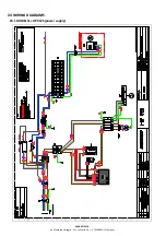
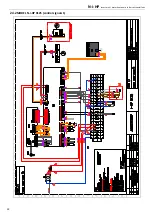
The
following
are
present
the
standard
connections.
Other
connections
and
configurations
are
shown
in
the
manual
control
(the
permissible
configurations
tables
for
user
and
installer).
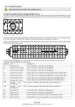
TERMINAL
TYPE
CONNECTION
AI1E
Analogue
input
NTC
ST3E
Terminal
input
for
remote
plant
temperature
probe
(optional)
AI1E
Analogue
input
NTC
ST3E
Terminal
input
for
remote
plant
temperature
probe
(optional)
AID1E
Digital
input
DI6E
expansion
board
Input
terminal
for
double
set
‐
point
consent
(only
if
Hi
‐
T
not
presents)
AID1E
Digital
input
DI6E
expansion
board
Input
terminal
for
double
set
‐
point
consent
(only
if
Hi
‐
T
not
presents)
DO1EN
Digital
output
230
Vac
(DO1E)
expansion
board
Neutral
terminal
(230V,
50Hz,
5A
resistive,
1
A
inductive)
for
power
on
the
contactor
coil
of
sanitary
integrative
heater
(not
supplied)
DO1E
Digital
output
230
Vac
(DO1E)
expansion
board
Neutral
terminal
(230V,
50Hz,
5A
resistive,
1
A
inductive)
for
power
on
the
contactor
coil
of
sanitary
integrative
heater
(not
supplied)
DO2EN
Digital
output
230
Vac
(DO2E)
expansion
board
Neutral
terminal
(230V,
50Hz,
5A
resistive,
1
A
inductive)
for
power
on
the
contactor
coil
of
sanitary
integrative
heater
(not
supplied)
DO2E
Digital
output
230
Vac
(DO2E)
expansion
board
Neutral
terminal
(230V,
50Hz,
5A
resistive,
1
A
inductive)
for
power
on
the
contactor
coil
of
sanitary
integrative
heater
(not
supplied)
DO3EN
Digital
output
230
Vac
(DO3E)
expansion
board
Neutral
terminal
(230V,
50Hz,
5A
resistive,
1
A
inductive)
for
boiler
consent
(voltage
output,
use
a
relay)
DO3E
Digital
output
230
Vac
(DO3E)
expansion
board
Neutral
terminal
(230V,
50Hz,
5A
resistive,
1
A
inductive)
for
boiler
consent
(voltage
output,
use
a
relay)
NO1E
Digital
output
230
Vac
(NO
contact)
expansion
board
Power
supply
phase
NO
terminal
(230V,
50Hz,
5A
resistive,
1
A
inductive)
double
setpoint
3
way
valve
for
radiant
panels
(optional)
(if
the
contact
is
active
the
valve
must
be
turn
to
floor
side)
N1E
Neutral
terminal
power
supply
(230V
AC)
double
setpoint
3
way
valve
for
radiant
panels
(optional)
NC1E
Digital
output
230
Vac
(NC
contact)
expansion
board
Power
supply
phase
NC
terminal
(230V,
50Hz,
5A
resistive,
1
A
inductive)
double
setpoint
3
way
valve
for
radiant
panels
(optional)
(if
the
contact
is
active
the
valve
must
be
turn
to
fancoil
side)
8
START
UP
Before
start
‐
up:
Check
out
the
availability
of
the
supplied
wiring
diagrams
and
manuals
of
the
installed
appliance.
Check
out
the
availability
of
the
electrical
and
hydraulic
diagrams
of
the
plant
in
which
the
unit
is
installed.
Check
that
the
shut
‐
off
valves
of
the
hydraulic
circuits
are
open.
Verify
that
the
hydraulic
circuit
has
been
charged
under
pressure
and
air
vented.
Check
out
that
all
hydraulic
connections
are
properly
installed
and
all
indications
on
unit
labels
are
respected.
Check
if
all
power
cables
are
properly
connected
and
all
terminals
are
tightly
fixed.
Check
if
the
electrical
connections
are
performed
according
to
the
norms
in
force
including
the
grounding
connection.
Check
if
the
voltage
is
that
shown
in
the
unit
labels.
Make
sure
the
voltage
is
within
the
limits
(±5%)
of
tolerance
range.
Check
if
the
electric
heaters
of
the
compressors
are
powered
correctly.
Make
sure
that
there
is
no
refrigerant
leak.
Be
sure
that
all
the
cover
panels
are
installed
in
their
proper
positions
and
locked
with
fastening
screws
before
start
up.
If
the
first
start
up
of
the
machine
does
not
turn
the
display
on
of
the
controller,
you
must
reverse
the
phase
sequence
of
the
power
supply
cable.
WARNING:
The
unit
must
be
connected
to
the
electrical
network
and
should
be
in
STAND
‐
BY
mode
(powered)
closing
the
general
switch
in
order
to
operate
the
crankcase
heaters
of
the
compressor
for
a
minimum
of
12
hours
before
start
up.
(the
heaters
are
automatically
powered
when
the
main
switch
is
switched
off).
The
crankcase
heaters
are
working
properly
if,
after
some
minutes,
the
temperature
of
crankcase’s
compressor
is
about
10°C
÷
15°C
higher
than
ambient
temperature.
WARNING:
Never
switch
off
the
unit
(for
a
temporary
stop)
by
switching
off
the
main
switch:
this
component
should
be
used
to
disconnect
the
unit
from
the
power
supply
only
for
lengthy
stoppages
(e.g.
seasonal
stoppages).
Besides,
failing
the
power
supply,
the
crankcase’s
heaters
are
not
supplied
thus
resulting
in
a
possible
breakdown
of
the

