background image


ADVANTIX


SPA


Via


Mansoldo


Gettuglio


Loc.


La


Macia


Z.A.I


37040


ARCOLE


(Verona)


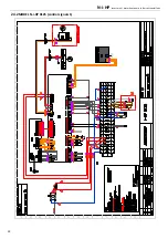
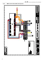
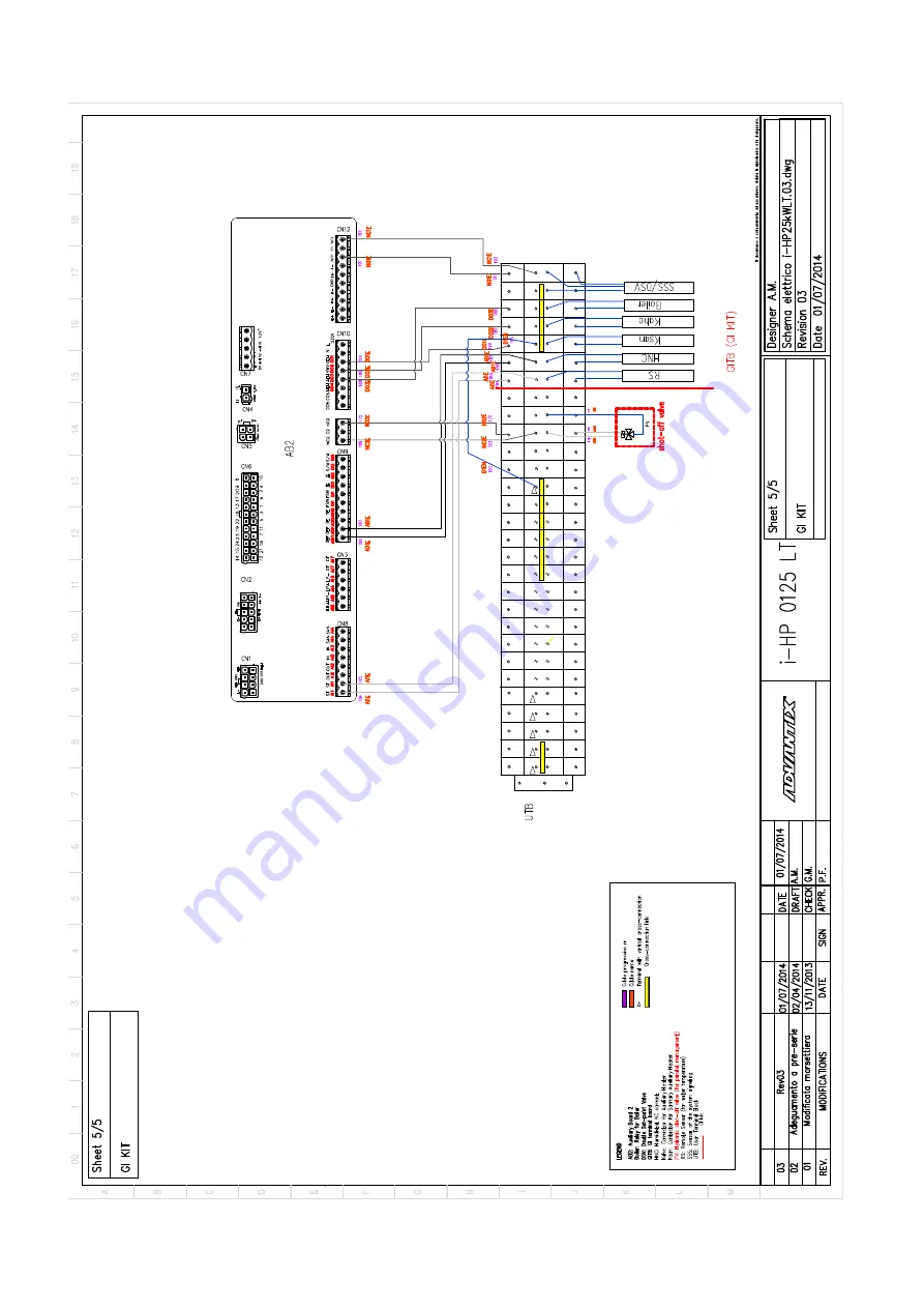
24.9


MODEL


N

i

HP

LT


0125


(GI


module


control


signals)


0V

0V

0V

0V

N1

N1

N1

N1

12V

12V

12V

12

V

5V

+

5V

+

A

I10+

A

I10+

A

I10-

A

I10-

AD

I2

AD

I2

AD

I2

AD

I2

DI

1

DI

1

DI

1

DI

1

DI

2

DI

2

DI

2

DI

2

DI

3

DI

3

DI

3

DI

3

DO

1

DO

2

DO

3

D

O

4

DO

5

DO

4N

DO

5N

DO

3

N

DO

1

N

DO

2

N

DO

4N

DO

3

N

DO

1

N

DO

2

N

DO

1

DO

2

DO

3

DO

4

DO

5N

DO

5

NC1

NC

1

N1

N2

N2

N1

NC

2

NO

2

NC2

NO

2

NO

1

NO

1

N2

E

N2

E

R-

R+

R-

R+

NC

2

E

NO

2E

NC

2

E

NO

2E

GN

D

R

GN

D

R

AI

1

E

AI

1

E

AD

I1

E

AD

I1

E

AD

I1

E

AD

I1

E

AI

1

E

AI

1

E

DO

1E

N

DO

1

E

PE

DO

1

E

DO

1E

N

DO

2E

N

DO

2

E

DO

2

E

DO

2E

N

DO

3

E

N

DO

3

E

DO

3

E

DO

3

E

N

N1

E

N1

E

NC

1E

NO

1

E

NO

1

E

NC

1E

N1

_3

N

1_2

N1

_1

N1

_4

L3_1

L3_2

L3_3

L3_4


Summary of Contents for i-HP 0235

Page 1: ...manual has been created for informative purpose The company declines any responsibility for the results of any projecting or any installation based on the explanations and or on the technical specific...

Page 2: ...e S rie USER S AND INSTALLER S MANUAL FOR INVERTER AIR WATER INDUSTRIALS HEAT PUMPS WITH AXIAL FANS Possible wasted electrical or electronic devices products should not be located together with normal...

Page 3: ...8 6 AVAILABLE VERSIONS SIZES AND ACCESSORIES 9 6 1 OPTIONAL ACCESSORIES 10 7 INSTALLATION 11 7 1 GENERALITY 11 7 2 LIFTING AND HANDLING 11 7 3 LOCATION AND MINIMUM TECHNICAL CLEARANCES 11 7 4 HYDRAUL...

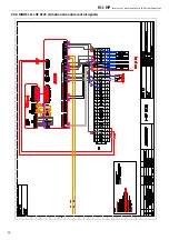
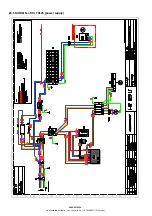
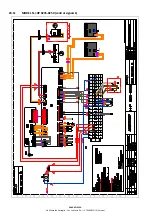
Page 4: ...S 29 24 WIRING DIAGRAMS 32 24 1 MODEL N I HP 0125 POWER SUPPLY 32 24 2 MODEL N I HP 0125 CONTROL SIGNALS 1 33 24 3 MODEL N I HP 0125 CONTROL SIGNALS 2 34 24 4 MODEL N I HP 0125 GI OPTIONAL MODULE CONT...

Page 5: ...ossible inaccuracies in the manual if due to printing or transcription errors The customer shall store any updated copy of the manual or parts of it delivered by the manufacturer as an attachment to t...

Page 6: ...nd safety including 89 391 CEE 89 686 CEE 89 655 CEE 86 188 CEE and 77 576 CEE directives Every employer shall implement such norms and ensure that workers to respect them It points out that Do not ta...

Page 7: ...rs AEL 8 h e 12 h TWA 1000 ml m for each of the two components Respiratory protection For rescue and maintenance operation in storage tanks use self contained respirator apparatus The vapors are heavi...

Page 8: ...he unit is in operation 5 4 AIR SIDE EXCHANGERS The air side heat exchanger is made up of copper pipes and aluminium fins The copper pipes diameter is 7 94 mm the thickness of the aluminium fins is 0...

Page 9: ...ntegrated modulating type circulator pump adopting a brushless motor suitable for chilled water utilization and directly managed by the controller on board 5 11 FAN SPEED CONTROL This type of regulati...

Page 10: ...ODE SIZE VERSION FACTORY INSTALLED ACCESSORIES XX10514 CT TA IV CI KA GI FAN SIL TR Heating capacity Water pipes configuration Vapour injection Hydronic configuration Antifreeze Kit Management module...

Page 11: ...SL accessory provides thermo acoustic insulators on compressors 2 The super silenced unit with SSL accessory provides thermo acoustic insulators on compressors and a special diffuser installed on the...

Page 12: ...unit is off The temperatures of heads and exhaust piping of the compressor are usually high Therefore be careful when working near condensing coils The aluminum fins are very sharp and can cause seri...

Page 13: ...m Should the water flow switch be altered or should the filter not be installed the warranty will no longer be valid The filter have to be kept clean so make sure it is clean after the unit has been i...

Page 14: ...diagram of the model N i HP 0125 C COMPRESSOR ST COMPRESSOR INLET TEMPERATURE DT COMPRESSOR OUTLET TEMPERATURE HP HIGH PRESSURE TRANSDUCER Pr HIGH PRESSURE FLOW SWITCH LP LOW PRESSURE TRANSDUCER LS L...

Page 15: ...URE OUT WATER OUTLET TEMPERATURE CP CAPILLARY NRV NO RETURN VALVE PV PRESSURE CHECK VALVE 7 5 3 Refrigerant diagram of the model N i HP LT 0125 C COMPRESSOR ST COMPRESSOR INLET TEMPERATURE DT COMPRESS...

Page 16: ...idual current circuit breaker choose a four pole one with a trigger threshold of 300 mA and delayed triggering super resistant characteristic K The machine must be installed in TN S TT power supply ea...

Page 17: ...DO3N DO4N DO5N N2 N2 DO2 DO1 DO3 DO4 DO5 N1 DO2N DO1N DO3N DO4N DO5N PE PE The connections indicated below are standard Other connections are reported in the manual of the controller table of configur...

Page 18: ...Digital output neutral 230 Vac Connections made in factory see wiring diagrams DO5 Digital output phase 230 Vac Connections made in factory see wiring diagrams NC1 Digital output 230 Vac with changeo...

Page 19: ...1E Digital output 230 Vac NC contact expansion board Power supply phase NC terminal 230V 50Hz 5A resistive 1 A inductive double setpoint 3 way valve for radiant panels optional if the contact is activ...

Page 20: ...operations re install the cover panels and fix them by means of screws The refrigerant circuits must not be filled with different gas other than that indicated on the nameplate The use of a different...

Page 21: ...37 3 38 3 36 3 34 Heating capacity 4 kW 25 23 27 1 25 2 27 1 37 91 40 8 37 9 40 8 48 55 52 1 48 7 52 3 Power input 4 kW 6 13 6 1 9 21 9 2 11 75 11 9 C O P 4 W W 4 12 4 13 4 12 4 12 4 13 4 10 Compresso...

Page 22: ...power input kW 0 42 0 55 0 91 Rated current input A 0 62 0 83 1 44 Speed r min 561 620 752 Rated air flow m3 s 5 00 5 56 6 94 Refrigerant Type R410A R410A R410A Refrigerant quantity kg 9 5 15 35 15 75...

Page 23: ...hnical data label sticked on right side panel of the unit 15 HEAT PUMPS AVAILABLE HEAD PRESSURE WITH INTEGRATED CIRCULATOR Below the characteristic curves corresponding to Head pressure Water flow wit...

Page 24: ...N i HP Inverter air water heat pump chillers with axial fans 23 15 3 MODEL N i HP 0250 16 WATER PUMP CURVES 16 1 MODELS N i HP 0125 0235 External control via PWM1 signal...

Page 25: ...SES CURVES OF THE HYDRONIC CIRCUIT We obtain the pressure head of the circulating pump from the sum of the head losses of the hydronic circuit and the available head pressure For example for the model...

Page 26: ...compressor rotation frequencies The special multi layer structure generates a thermal insulation which reduces at very low outside temperatures the heat losses of 2 compared to a standard insulation 1...

Page 27: ...uests The maximum temperature that can be maintained at the outlet of the evaporator is 25 C Higher temperatures up to a maximum of 40 C can anyway be tolerated during transitions and start up phases...

Page 28: ...1 2 1 33 CCF Capacity correction factor IPCF Input power correction factor WFCF Water flow rate correction factor PDCF Pressure drops correction factor The water flow rate and pressure drop correction...

Page 29: ...E Verona 22 DIMENSIONS 22 1 MODELS N I HWAK WP V2 V2 06 IN OUT 2 F By inserting the optional element AxiTop the maximum height changes from 1741 mm to 1906 mm The maximum dimensions of the packaged un...

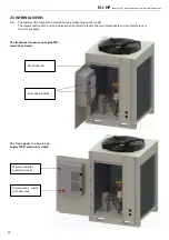
Page 30: ...representation of the units is indicative and useful to present the main components and can therefore vary From it s available The front panel is open at an angle of 90 electric box closed The front p...

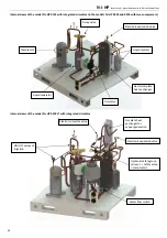
Page 31: ...ller User terminal block Terminal block on board unit Support boards Transformer Slave controller mounted only on the versions with injection and or with plant management optional module Driver boards...

Page 32: ...rnal views of the model N i HP 0250 LT with integrated circulator Compressor Liquid separator Liquid receiver 4 way valve Electronic expansion valve Circulator Gas water plate heat exchanger ON OFF va...

Page 33: ...V L3_1 N1 N1 N1 N1 ADI2 ADI2 ADI2 ADI2 DI3 DO4 DI3 DI3 DI3 DO4N DO4N DO4 DI2 DI2 DI2 DI2 DO5 DO5N DO5N DO5 NO1 NC1 NC1 NO1 N2 N1 N2 N1 NO2 NC2 NC2 NO2 R R R R 12V 12V 12V 12V AI10 AI10 AI10 AI10 5 GND...

Page 34: ...0V 0V N1_2 N1_1 N1_4 0V AI10 AI10 AI10 AI10 DO4 DO5 DO4N DO4N DO4 DO5N DO5N DO5 N1 N2 N2 N1 NC2 NO2 NC2 NO2 R R R R L3_1 N1 N1 N1 N1 ADI2 ADI2 ADI2 ADI2 DI3 DI3 DI3 DI3 DI2 DI2 DI2 DI2 NO1 NO1 5V 5V...

Page 35: ...N1 12V 12V 12V 12V 5V 5V AI10 AI10 AI10 AI10 ADI2 ADI2 ADI2 ADI2 DI1 DI1 DI1 DI1 DI2 DI2 DI2 DI2 DI3 DI3 DI3 DI3 DO1 DO2 DO3 DO4 DO5 DO4N DO5N DO3N DO1N DO2N DO4N DO3N DO1N DO2N DO1 DO2 DO3 DO4 DO5N...

Page 36: ...DI1 DI1 DI1 DI1 DI2 DI2 DI2 DI2 DI3 DI3 DI3 DI3 DO1 DO2 DO3 DO4 DO5 DO4N DO5N DO3N DO1N DO2N DO4N DO3N DO1N DO2N DO1 DO2 DO3 DO4 DO5N DO5 NC1 NC1 N1 N2 N2 N1 NC2 NO2 NC2 NO2 NO1 NO1 N2E N2E R R R R NC...

Page 37: ...1 N1 N1 N1 ADI2 ADI2 ADI2 ADI2 DI3 DO4 DI3 DI3 DI3 DO4N DO4N DO4 DI2 DI2 DI2 DI2 DO5 DO5N DO5N DO5 NO1 NC1 NC1 NO1 N2 N1 N2 N1 NO2 NC2 NC2 NO2 R R R R 12V 12V 12V 12V AI10 AI10 AI10 AI10 5 GNDR GNDR 5...

Page 38: ...0V 0V 0V N1_2 N1_1 N1_4 0V AI10 AI10 AI10 AI10 DO4 DO5 DO4N DO4N DO4 DO5N DO5N DO5 N1 N2 N2 N1 NC2 NO2 NC2 NO2 R R R R L3_1 N1 N1 N1 N1 ADI2 ADI2 ADI2 ADI2 DI3 DI3 DI3 DI3 DI2 DI2 DI2 DI2 NO1 NO1 5V 5...

Page 39: ...1 N1 12V 12V 12V 12V 5V 5V AI10 AI10 AI10 AI10 ADI2 ADI2 ADI2 ADI2 DI1 DI1 DI1 DI1 DI2 DI2 DI2 DI2 DI3 DI3 DI3 DI3 DO1 DO2 DO3 DO4 DO5 DO4N DO5N DO3N DO1N DO2N DO4N DO3N DO1N DO2N DO1 DO2 DO3 DO4 DO5N...

Page 40: ...N1 12V 12V 12V 12V 5V 5V AI10 AI10 AI10 AI10 ADI2 ADI2 ADI2 ADI2 DI1 DI1 DI1 DI1 DI2 DI2 DI2 DI2 DI3 DI3 DI3 DI3 DO1 DO2 DO3 DO4 DO5 DO4N DO5N DO3N DO1N DO2N DO4N DO3N DO1N DO2N DO1 DO2 DO3 DO4 DO5N...

Page 41: ...2 DI1 DI1 DI1 DI1 DI2 DI2 DI2 DI2 DI3 DI3 DI3 DI3 DO1 DO2 DO3 DO4 DO5 DO4N DO5N DO3N DO1N DO2N DO4N DO3N DO1N DO2N DO1 DO2 DO3 DO4 DO5N DO5 NC1 NC1 N1 N2 N2 N1 NC2 NO2 NC2 NO2 NO1 NO1 N2E N2E R R R R...

Page 42: ...I2 ADI2 ADI2 ADI2 DI3 DO4 DI3 DI3 DI3 DO4N DO4N DO4 DI2 DI2 DI2 DI2 DO5 DO5N DO5N DO5 NO1 NC1 NC1 NO1 N2 N1 N2 N1 NO2 NC2 NC2 NO2 R R R R 12V 12V 12V 12V AI10 AI10 AI10 AI10 5 GNDR GNDR 5 DO3 DO3N DO3...

Page 43: ...1 0V 0V 0V N1_2 N1_1 N1_4 0V AI10 AI10 AI10 AI10 DO4 DO5 DO4N DO4N DO4 DO5N DO5N DO5 N1 N2 N2 N1 NC2 NO2 NC2 NO2 R R R R L3_1 N1 N1 N1 N1 ADI2 ADI2 ADI2 ADI2 DI3 DI3 DI3 DI3 DI2 DI2 DI2 DI2 NO1 NO1 5V...

Page 44: ...12V 12V 12V 12V 5V 5V AI10 AI10 AI10 AI10 ADI2 ADI2 ADI2 ADI2 DI1 DI1 DI1 DI1 DI2 DI2 DI2 DI2 DI3 DI3 DI3 DI3 DO1 DO2 DO3 DO4 DO5 DO4N DO5N DO3N DO1N DO2N DO4N DO3N DO1N DO2N DO1 DO2 DO3 DO4 DO5N DO5...

Page 45: ...I2 ADI2 DI1 DI1 DI1 DI1 DI2 DI2 DI2 DI2 DI3 DI3 DI3 DI3 DO1 DO2 DO3 DO4 DO5 DO4N DO5N DO3N DO1N DO2N DO4N DO3N DO1N DO2N DO1 DO2 DO3 DO4 DO5N DO5 NC1 NC1 N1 N2 N2 N1 NC2 NO2 NC2 NO2 NO1 NO1 N2E N2E R...

Page 46: ...ADI2 ADI2 ADI2 ADI2 DI3 DO4 DI3 DI3 DI3 DO4N DO4N DO4 DI2 DI2 DI2 DI2 DO5 DO5N DO5N DO5 NO1 NC1 NC1 NO1 N2 N1 N2 N1 NO2 NC2 NC2 NO2 R R R R 12V 12V 12V 12V AI10 AI10 AI10 AI10 5 GNDR GNDR 5 DO3 DO3N D...

Page 47: ...C1 0V 0V 0V N1_2 N1_1 N1_4 0V AI10 AI10 AI10 AI10 DO4 DO5 DO4N DO4N DO4 DO5N DO5N DO5 N1 N2 N2 N1 NC2 NO2 NC2 NO2 R R R R L3_1 N1 N1 N1 N1 ADI2 ADI2 ADI2 ADI2 DI3 DI3 DI3 DI3 DI2 DI2 DI2 DI2 NO1 NO1 5...

Page 48: ...N1 12V 12V 12V 12V 5V 5V AI10 AI10 AI10 AI10 ADI2 ADI2 ADI2 ADI2 DI1 DI1 DI1 DI1 DI2 DI2 DI2 DI2 DI3 DI3 DI3 DI3 DO1 DO2 DO3 DO4 DO5 DO4N DO5N DO3N DO1N DO2N DO4N DO3N DO1N DO2N DO1 DO2 DO3 DO4 DO5N D...

Page 49: ...N1 N1 N1 N1 12V 12V 12V 12V 5V 5V AI10 AI10 AI10 AI10 ADI2 ADI2 ADI2 ADI2 DI1 DI1 DI1 DI1 DI2 DI2 DI2 DI2 DI3 DI3 DI3 DI3 DO1 DO2 DO3 DO4 DO5 DO4N DO5N DO3N DO1N DO2N DO4N DO3N DO1N DO2N DO1 DO2 DO3 D...

Page 50: ...DI1 DI1 DI1 DI1 DI2 DI2 DI2 DI2 DI3 DI3 DI3 DI3 DO1 DO2 DO3 DO4 DO5 DO4N DO5N DO3N DO1N DO2N DO4N DO3N DO1N DO2N DO1 DO2 DO3 DO4 DO5N DO5 NC1 NC1 N1 N2 N2 N1 NC2 NO2 NC2 NO2 NO1 NO1 N2E N2E R R R R NC...

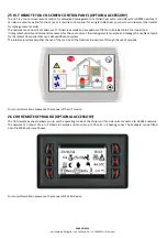
Page 51: ...humidity and temperature sensors for the environment thermohygrometer analysis and manage the double setpoint for the radiant floor panel that use a dehumidification system The intuitive interface si...

Page 52: ...ssible configurations there is a handbook that is a technical book containing a series of recommended drawings of plants that have been highlighted regarding the installation configuration of our high...

Page 53: ...ADVANTIX SPA Via Mansoldo Gettuglio Loc La Macia Z A I 37040 ARCOLE Verona NOTES...

Page 54: ...N i HP Inverter air water heat pump chillers with axial fans 53...

Page 55: ......

Page 56: ...Serial number...

Reviews: