17
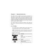
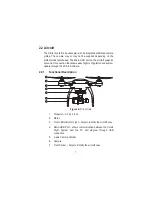
1.
Mounting Rack
2.
Vibration Absorber
3.
Anti-drop Lock Pin
A.
Press the pin through the hole at the corner of the
gimbal’s mounting rack with the Vibration Absorber in
between;
B.
Press the stud from the bottom up to lock the pin.
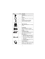
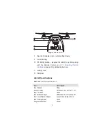
4.
Aircraft Communication Port
5.
Camera Connector
6.
Micro-USB Port – connects to the PC using the Micro-USB
cable supplied for camera file transfer. Do not disconnect the
camera from the gimbal while transferring.
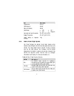
Camera Gimbal Specifications
Table 2-10
Camera Gimbal Specifications
Item
Descriptions
Operating Current
340mA@12V (Camera Off)
600mA@12V (Camera On)
Operating
Environment Temperature
0
q
C~45
q
C
Control Accuracy
Tilt/Roll:
r
0.02
q
Yaw:
r
0.03
q
Controllable Range
Pitch: 0
q
~90
q
(-130~+45°)
Maximum Angular Velocity
90
q
/s (
r
150°/S)
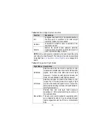
NOTE:
The Camera Gimbal comes with a gimbal lock attached
which protects the gimbal from incidental rotation to avoid damage.
Remove the clamp before powering up the aircraft (see
Figure 3-1
on page 27).

