6.0 TENSION CONTROL
www.maxcessintl.com
MAGPOWR Spyder-Plus-S1 Tension Control
MI 850A351 1 C
Page 16 of 68
6.2.2.1
CONTROL TYPE
Select the
Load Cell
control type. Load cell systems must use a torque device, which can be a motor in torque
mode.
6.2.2.2
SYSTEM TYPE
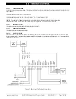
Select the appropriate system type for the application; rewind, unwind, or one of the point-to-point types. See
Figure 6 for information on the point-to-point types.
6.2.2.3
DIAMETER USED
Select the diameter type either estimated or an external voltage proportional to diameter. For calibrating diameter
see section 6.5 if diameter type is
Voltage
and section 9.2 if diameter type is
Estimated
.
6.2.2.4
INERTIA COMPENSATION USED
Select whether inertia compensation is used during stopping. This helps to keep the tension constant during
stopping. See section 6.6 on setting up and using inertia compensation.
6.2.2.5
HOLD LEVEL CHANGE WITH
Hold Level Output during Hold mode can be a fixed value, or can vary with last running output multiplied by the
Hold Level Multiplier, or can vary based on diameter and or tension. Select the choice needed for the application;
None, Output, Diameter, Tension, or Diameter and Tension. See section 9.6.13 to calibrate hold level changes
when the choice is Diameter, Tension, or Diameter and Tension. See section 9.6.14 to enter the Hold level
multiplier when the choice is Output.
6.2.2.6
OUTPUT RANGE
Select the main output range. For a main output range of either 0-10 VDC or 4-20 mADC select
NORMAL
. For the
–10 to +10 VDC range, select
–10 V to +10 V
. The software is factory calibrated for the 0-10 VDC and the -10 to
+10 VDC output ranges. See Section 9.4 for recalibrating the output when using the 4-20 mADC range.
See Figure 4 for jumper settings.
6.2.2 CONFIGURE MENU
Navigate to the
Configure
menu. Press
. This section describes all
the screens in the Configure menu. This menu contains screens which
configure various options.
Summary of Contents for MAGPOWR Spyder-Plus-S1
Page 2: ......


