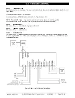
6.0 TENSION CONTROL
www.maxcessintl.com
MAGPOWR Spyder-Plus-S1 Tension Control
MI 850A351 1 C
Page 17 of 68
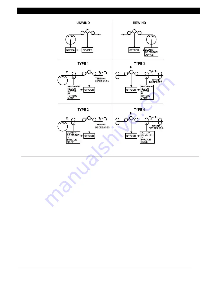
Figure 6. Load Cell System Types
6.2.2.7
SETPOINT SOURCE
Select the tension setpoint source. The tension setpoint is either the tension input (Term.16) or the Ethernet. The
software is factory calibrated for using a 1K to 10K potentiometer on Term.15 through Term.17 with the wiper on
Term.16. When using an external 0-10 VDC voltage source see Section 9.3 for recalibrating the tension setpoint
input.
6.2.2.8
DIGITAL INPUT ACTIVE LEVEL
The digital control inputs may be either Active Low or Active High. The software is factory configured for Active Low
inputs. See Section 5.2 and Figure 4.
6.2.2.9
INITIAL SCREEN
The first screen after power-up is the
Operator Loop
screen. This parameter allows the initial power-up screen to
be changed to either the
Tension
screen, Section 6.2.1.1 or the
Output Level
screen, Section 6.2.1.5.
6.2.2.10
NUMERIC UPDATE RATE
This parameter controls the filtering for the numeric actual tension and the actual output displays. Default values
work well in most applications.
6.2.2.11
BAR GRAPH UPDATE RATE
This parameter controls the filtering for the bar graph actual tension and the actual output displays. Default values
work well in most applications.
6.2.2.12
SCREEN CONTRAST
Adjusts the screen contrast. See Section 10.1, General Problems, when screen shows no characters.
Summary of Contents for MAGPOWR Spyder-Plus-S1
Page 2: ......


