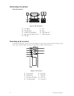
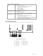
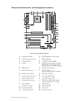
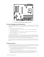
background image

10

Server Description

11

MAXDATA PLATINUM 220 Server

Processor

The S875WP1-E server board supports a single Intel

®

 Pentium

®

 4 processor with an mPGA478 socket.  

The processor connects to the server board through the mPGA478 socket. The Intel

®

 Pentium

®

 4 

processor can be removed and replaced to accommodate a supported higher speed processor. 

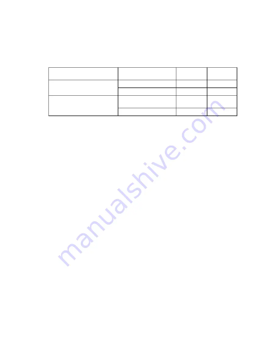
The server board S875WP1-E supports the following processors.

Table 2. Supported Processors

Type

Designation 

System Bus 

L2 Cache 
Size

Pentium

®

 4 processor with Hyper-

Threading (HT) Technology

2.40, 2.60, 2.80, and 3.0 GHz

800 MHz

512 KB

3.06 GHz

533 MHz

512 KB

Pentium

®

 4 processor

2.0, 2.26, 2.4B, 2.53, 2.66 and 
2.80 GHz

533 MHz

512 KB

2.0, 2.4 GHz

400 MHz

512 KB

Memory

The S875WP1-E server board contains four 184-pin DIMM sockets and supports up to four DDR 
SDRAM  DIMMs.  The  minimum  supported  memory  configuration  is  128  MB  and  the  maximum 
configurable memory size is 4 GB with stacked unbuffered DDR266/333/400 ECC DIMMs. 

Supported memory configurations are as follows:

Up to four dual-channel 184-pin Double Data Rate (DDR) SDRAM DIMMs connectors with gold-plated 
contacts. Supported memory configuration are:

1.   DDR400: To run DDR400 memory at full speed requires an Intel

®

 Pentium

®

 4 processor with 

      800 MHz front side bus (FSB) frequency.

2.   DDR333: To run DDR333 memory at full speed requires an Intel

®

 Pentium

®

 4 processor with 

      533 MHz FSB frequency. DDR333 memory will run at 320 MHz frequency when using an 
      Intel

®

 Pentium

®

 4 processor with 800 MHz FSB frequency.

3.   DDR266: DDR266 memory may only be used with an Intel

®

 Pentium

®

 4 processor with

      400 MHz or 533 MHz FSB frequency only.

Support for:

1.   Single-channel memory.
2.   Unbuffered, single or double-sided DIMMs.
3.   Serial Presence Detect (SPD) memory only.
4.   Support for Suspend to RAM (STR), S3 ACPI state.
5.   ECC and non-ECC RAM.
6.   2.5V memory.

Support for 128 MB, 256 MB, and 512 MB memory technologies for the following memory configu-
rations:
1.   Up to 1.0 GB utilizing 128 MB technology.
2.   Up to 2.0 GB utilizing 256 MB technology.
3.   Up to 4.0 GB utilizing 512 MB technology.
Only DIMMs tested and qualified by Intel

®

 or a designated memory test vendor will be supported 

on the board. Note that all DIMMs are supported by design, but only fully qualified DIMMs will be 
supported. Mixed mode DDR DS-DIMMs (x8 and x16 on the same DIMM) is not supported.  

Summary of Contents for PLATINUM 110

Page 1: ...System Manual MAXDATA PLATINUM 220 Server...

Page 2: ...2 Contents...

Page 3: ...allel Port 14 Floppy Drive Controller 14 Keyboard and Mouse Connectors 14 USB 14 High Speed USB 2 0 Support 14 Legacy USB Support 14 PCI I O Subsystem 15 Data Storage 16 Serial ATA SATA 16 IDE Interfa...

Page 4: ...Installation Requirements 31 Prevent Power Supply Overload 31 Place Battery Marking 31 Use Only for Intended Applications 31 Figures 1 Rear connectors 6 2 The Controls 6 3 Back Panel Connectors 8 4 S...

Page 5: ...t trip hazards When you save data to your server s hard disks or to a floppy disk they are stored as magnetic information on the media Make sure that they are not damaged by magnetic or electromagneti...

Page 6: ...ort A Serieller Port A I USB Connector 2 E VGA port Powering up the system At the front of the case you can find the neccessary controls like power button reset button and the HDD Leds Press the power...

Page 7: ...ts Intel 82802AC 8 megabit Firmware Hub FWH I O Control SMSC LPC47M172 super I O controller Peripheral Interfaces Four external USB ports on the back panel with an additional internal header which pro...

Page 8: ...ent Hardware monitor with Four fan sensing inputs used to monitor fan activity Remote diode temperature sensing Intel Precision CoolingTechnology fan speed control that auto matically adjusts chassis...

Page 9: ...SATA A2 SATA A3 SATA A1 E DIMM Sockets T Chassis Intrusion Header F Main Power Connector U PCI 32 33 Slots 1 3 slots numbered from top to bottom G Floppy Drive Connector V System Fan 3 Header H Auxili...

Page 10: ...onnectors with gold plated contacts Supported memory configuration are 1 DDR400 To run DDR400 memory at full speed requires an Intel Pentium 4 processor with 800 MHz front side bus FSB frequency 2 DDR...

Page 11: ...isabled or enabled by BIOS It is enabled by default The MCH controls the Intel 82547EI from the CSA interface The MCH provides the following An integrated DDR memory controller with auto detection Sup...

Page 12: ...ler The S875WP1 E server board provides an ATI Rage XL PCI graphics accelerator along with 8 MB of video SDRAM and support circuitry for an embedded SVGA video subsystem The ATI Rage XL chip contains...

Page 13: ...4 43 60 70 72 Supported Supported 1600 x 1200 60 66 76 85 Supported Super I O The SMSC LPC47M172 I O Controller provides the following features Low pin count LPC interface 3 3V operation One serial po...

Page 14: ...the requirements for a full speed USB device Computer systems that have an unshielded cable attached to a USB port might not meet FCC Class B requirements even if no device or a low speed USB device...

Page 15: ...fter the operating system loads the USB drivers all legacy and non legacy USB devices are recognized by the operating system and Legacy USB support from the BIOS is no longer used To install an operat...

Page 16: ...ting host and target throttling and transfer rates of up to 33 MB sec ATA 100 66 DMA protocol on IDE bus supporting host and target throttling and transfer rates of up to 100 MB sec The ATA 100 66 pro...

Page 17: ...liant physical layer interface IEEE 802 3ab auto negotiation support Low power less than 350mW in active transmit mode Reduced power in unplugged mode less than 50mW Automatic detection of unplugged m...

Page 18: ...s spin down the system fans stop and all processing is halted In this state the power supply is still on and the processors still dissipate some power so the power supply fan and processor fans are st...

Page 19: ...the system state from the disk and resumes normal operation This state assumes that no hardware changes were made to the system while it was off S5 Soft off Only the RTC section of the chipset is run...

Page 20: ...monitors network traffic at the Media Independent Interface Upon detecting a Magic Packet frame the LAN subsystem asserts a wake up signal that wakes up the computer from ACPI S1 S3 S4 and S5 state De...

Page 21: ...power supply The total amount of standby current required depends on the wake devices supported and manufacturing options Power Connector When used with an ATX12V or EPS12V compliant power supply tha...

Page 22: ...andby line for the power supply must be capable of providing adequate 5V standby current Failure to provide adequate standby current when implementing Instantly Available PC technology can damage the...

Page 23: ...rdware monitoring that alerts a system administrator if a hardware problem occurs on an Intel Server Board S875WP1 E Based system The LDCM software is for use with Windows 2000 Server and Windows 2000...

Page 24: ...or Password Enter Password Supervisor or user Supervisor or user Note If no password is set any user can change all Setup options Real Time Clock CMOS SRAM and Battery The real time clock provides a t...

Page 25: ...ns 1 and 2 7 Replace the chassis cover and re attach the AC power cables 8 Power on the server 9 Reconfigure settings as necessary BIOS The S875WP1 E server board uses an Intel AMI BIOS that is stored...

Page 26: ...auto configuration options by specifying manual configuration in the BIOS Setup program To use ATA 66 100 features the following items are required An ATA 66 100 peripheral device An ATA 66 100 compa...

Page 27: ...time Disable Quiet Boot which eliminates display of the logo splash screen This could save several seconds of painting complex graphic images and changing video modes Enabled Intel Rapid BIOS Boot Thi...

Page 28: ...28 Server Description...

Page 29: ...gnetic compatibility EMC regulations when installed a compatible Intel host system For information on compatible host system s refer to Intel s Server Builder website or contact your local Intel repre...

Page 30: ...the receiver is connected Consult the dealer or an experienced radio TV technician for help Any changes or modifications not expressly approved by the grantee of this device could void the user s aut...

Page 31: ...that the calculated total current loads of all the modules within the computer is less than the output current rating of each of the power supplies output circuits Place Battery Marking There is insuf...

Reviews: