


12
Server Description
13
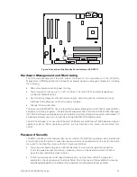
MAXDATA PLATINUM 220 Server
Video
The server board S875WP1-E contains two separate, mutually exclusive graphics subsystems. You
can use either the AGP connector or the ATI Rage XL video controller. When an AGP card is installed,
the integrated 8 MB video controller is disabled.
AGP Connector
AGP is a high-performance interface for graphics-intensive applications. AGP is independent of the
PCI bus and is intended for exclusive use with graphical display devices. The AGP bus follows the
AGP 3.0 specification.
The AGP connector on the server board S875WP1-E supports the following:
• 2X, 4X, or 8X AGP protocol.
• 1.5 V add-in cards only.
• Maximum bus bandwidth of 2.13 GB/sec
NOTE
The AGP connector is keyed for 1.5V AGP cards only. Do not attempt to install a legacy 3.3V AGP
card. The AGP connector is not mechanically compatible with legacy 3.3 V AGP cards.
ATI Rage XL Video Controller
The S875WP1-E server board provides an ATI Rage XL PCI graphics accelerator, along with 8 MB
of video SDRAM and support circuitry for an embedded SVGA video subsystem. The ATI Rage XL
chip contains a SVGA video controller, clock generator, 2D and 3D engine, and RAMDAC in a 272-pin
PBGA. One 2Mx32 SDRAM chip provides 8 MB of video memory.
The SVGA subsystem supports a variety of modes, up to 1600 x 1200 resolution in 8/16/24/32 bpp
modes under 2D, and up to 1024 x 768 resolution in 8/16/24/32 bpp modes under 3D. It also supports
both CRT and LCD monitors up to 100 Hz vertical refresh rate.
The server board S875WP1-E provides a standard 15-pin VGA connector and supports disabling of
the on-board video through the BIOS Setup menu or when a plug-in video card is installed in the AGP
slot or any of the PCI slots.
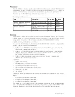
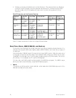
Video Modes
The Rage XL chip supports all standard IBM VGA modes. The following table shows the 2D/3D modes
supported for both CRT and LCD. The table specifies the minimum memory requirement for various
display resolution, refresh rates, and color depths.
Summary of Contents for PLATINUM 110
Page 1: ...System Manual MAXDATA PLATINUM 220 Server...
Page 2: ...2 Contents...
Page 28: ...28 Server Description...


