background image

20

21

MAXDATA SR1202 M1 – Technical User Guide

Introduction

20

21

MAXDATA SR1202 M1 – Technical User Guide

Introduction

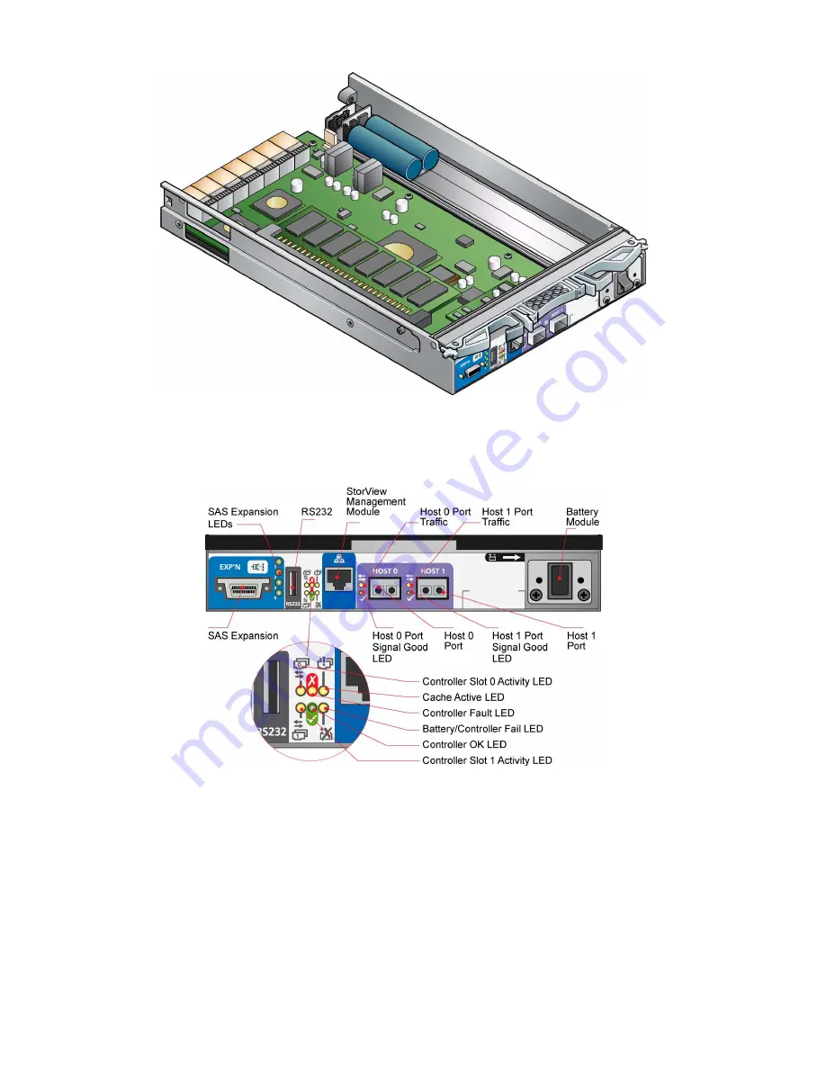
Figure 17. SR1202 RAID Controller Module

Figure 18. SR1202 Module Front Panel

The recommended configurations are shown in sections “Fibre Channel Interace” on page 31 and 
“Enclosure Expansion” on page 33.

Summary of Contents for SR1202 M1

Page 1: ...Technical User Guide MAXDATA SR1202 M1...

Page 2: ...2 Contents...

Page 3: ...a Security 12 Special Tools and Equipment 12 2 Introduction 13 SR1202 Enclosure Platform 13 The Enclosure Core Product 14 Enclosure Chassis 14 Operator s Panel 15 Alarms 16 Visible Alarms 16 Audible A...

Page 4: ...rangement 33 Drive Start 33 Engaging the Anti tamper Locks 33 Power Cord Connection 34 Parts Check List 34 Procedure 34 Grounding Checks 35 4 Operation 37 Before You Begin 37 Power On 37 Starting the...

Page 5: ...RAID Controller Module 52 Battery Module 53 Removing a Battery Module 53 Installing a Battery Module 54 Drive Carrier Module 55 Removing a Drive Carrier Module 55 Installing a Drive Carrier Module 56...

Page 6: ...Controller Connections 31 26 Dual Host Dual Controller Connections 31 27 Dual Host Dual Controller Connections Single HBA 32 28 Dual Host Dual Controller and Single Switch Connections Dual HBA 32 29...

Page 7: ...nto which you are installing your SR1202 Enclosure Platform If you do not have these skills or are not confident with the instructions in this guide do not proceed with the installation International...

Page 8: ...evice may not cause harmful interference and 2 this device must accept any interference received including interference that may cause undesired operation European Regulations This equipment complies...

Page 9: ...n Module Caution Label Do not operate with modules missing SR1202 enclosures must only be operated from a power supply input voltage range of 100 to 240 VAC Figure 6 PSU Ratings Label The plugs on the...

Page 10: ...l specification WARNING Do not remove covers from the Power Supply module Danger of electric shock inside Return the Power Supply module to your supplier for repair Figure 9 PSU Safety Label Electric...

Page 11: ...al use When loading a rack with the units fill the rack from the bottom up and empty from the top down System must be operated with low pressure rear exhaust installation Back pressure created by rack...

Page 12: ...tion Each enclosure contains up to 12 removable disk drive modules Disk units are fragile Handle them with care and keep them away from strong magnetic fields All the supplied plug in modules dummy ca...

Page 13: ...ther 3 0 Gb s direct dock SAS disk drives 3 0 Gb s direct dock SATA disk drives or 3 0 Gb s dual path SATA disk drives via an active active SATA mux transition card IMPORTANT Mixing of SAS and SATA dr...

Page 14: ...ng a Backplane printed circuit board PCB and module runner system The chassis front panel incorporates an integral Operator s Ops Panel The Backplane PCB provides logic level signal and low voltage po...

Page 15: ...ps Panel provides the user with a high level indication of the operation of the Enclosure Please refer to Table 9 Ops Panel LED States on page 41 for details of the LED status conditions CAUTION The O...

Page 16: ...dicates failure of a drive module The module failing will be indicated by the Fault LED seeTable 11 on page 43 Box Identity Constant Blue enclosure identity The user can illuminate this via the Manage...

Page 17: ...or 2 x SR1202 RAID Controller Modules Up to 12 Drive Carrier modules Dummy Drive Carrier modules as required NOTE No drive bays should be left completely empty dummy carriers and or blank modules mus...

Page 18: ...only take a few minutes to perform but must be completed within 10 minutes from removal of the failed module Cooling Module The Cooling Module provides system cooling thermal monitoring and control fu...

Page 19: ...odules provide enclosure management interfacing to devices on the Backplane PSU SR1202 RAID Controller Module and Ops Panel to monitor internal functions These processors operate in a dual active conf...

Page 20: ...20 Introduction Figure 17 SR1202 RAID Controller Module Figure 18 SR1202 Module Front Panel The recommended configurations are shown in sections Fibre Channel Interace on page 31 and Enclosure Expans...

Page 21: ...ch is installed on the SMM is a full featured graphical HTML based software suite designed to configure manage and monitor the SR1202 RAID Controller Module Storage Solution Battery Module The SR1202...

Page 22: ...e 1 0 inch high 3 5 inch form factor disk drive in its carrier The carrier has mounting locations for SAS or SATA drives The front cap also supports an ergonomic handle which provides the following fu...

Page 23: ...f the handle These are provided to disable the normal pinch latch action of the carrier handle Figure 22 Anti tamper Lock Dummy Carrier Modules Dummy carrier modules are provided for fitting in all un...

Page 24: ...s is used with this product Weight Maximum Con guration 32 kg 70 4 lb Empty Enclosure 9 kg 19 8 lb AC Power 350 W PSU Voltage Range 100 240 VAC Rated Frequency 50 60 Hz Inrush Current 30 A 230 VAC Pow...

Page 25: ...ational Vertical axis 5 g peak 1 2 sine 10 ms Shock Non Operational 30 g 10 ms 1 2 sine Vibration Operational 0 21 grms 5 500 Hz Random Vibration Non Operational 1 04 grms 2 200 Hz Random Vibration Re...

Page 26: ...ache Active Amber Active cache contents Battery Controller Fail Amber Fault in battery or charger operation of controller Host 0 Port Signal Good Green When ON the LED denotes that incoming FC signal...

Page 27: ...f SR1202 RAID Controller Module configurations Table 5 Enclosure System Configuration Module Location Drive Bays ALL drive bays must be fitted with a drive carrier module or dummy drive carrier module...

Page 28: ...An SR1202 enclosure with all component parts installed is too heavy for a single person to safely install alone into a Rack cabinet The following procedures describe the installation of an SR1202 encl...

Page 29: ...rack you are using Parts Check List Rack Mounting Rail Kit Installation Procedure Please see detail drawings supplied with the rack mounting rail kit for assembly details Latch both sides Left hand as...

Page 30: ...torView comprises the StorView Server which runs as a background service and is responsible for managing the installed modules The StorView Server discovers system storage devices manages and distribu...

Page 31: ...ired with Fibre Channel architecture and any drive may be hot plugged during operation Each SR1202 RAID Controller Module can be connected to up to 2 independent Host Bus Adaptors or switch ports Some...

Page 32: ...32 Getting Started Figure 27 Dual Host Dual Controller Connections Single HBA Figure 28 Dual Host Dual Controller and Single Switch Connections Dual HBA Figure 29 Dual Host Dual Controller and Dual S...

Page 33: ...eferenced by their location as shown in Table 6 Drives are numbered column row Table 6 Drive Slot Arrangement Enclosure Front View Column row 1 2 3 4 1 Drive 1 Drive 2 Drive 3 Drive 4 2 Drive 5 Drive...

Page 34: ...le in the aperture beside the key NOTE A drive carrier cannot be installed if its anti tamper lock is activated outside the Enclosure Power Cord Connection Parts Check List Power cord to requisite loc...

Page 35: ...he SR1202 power cord to the rack distribution and the enclosure If a direct connection is made with the SR1202 power cord ensure that it is connected to the enclosure WARNING Some electrical circuits...

Page 36: ...36...

Page 37: ...tioning correctly all other Ops Panel LEDs are off If any LEDs show Amber then a problem exists and the procedure in Chapter 5 should be followed IMPORTANT If AC power is lost for any reason on restor...

Page 38: ...l be preserved by the internal battery It is therefore recommended that especially if the unit is to be powered down for extended periods the controller is shut down prior to powering off the enclosur...

Page 39: ...ecognize the SR1202 Enclosure 1 Check that the FC interface cables from the SR1202 enclosure to the host computer are fitted correctly 2 Check that the LEDs on all installed drive carrier modules are...

Page 40: ...ply LEDs Power On OK Green Module Fault Amber Status Off Off No AC power either PSU Off On No AC power this PSU only Off On PSU Fault over temp over volts over current PSU fan fail On Off AC present P...

Page 41: ...LED or Cooling Module Fault LED Any PSU Fault or Fan Fault Over or Under temperature On On X X RAID Controller Fault LED ESI processor A failed On On X X RAID Controller Fault LED ESI processor B fail...

Page 42: ...controller Host 0 Port Signal Good Green When ON the LED denotes that incoming FC signal is good Host 1 Port Signal Good Green When ON the LED denotes that incoming FC signal is good Host 0 PortTraf...

Page 43: ...utton while no faults are present While the test is running all LEDs will flash Drive Carrier Module Faults Disk drive status is monitored by a green LED and an amber LED mounted on the front of each...

Page 44: ...ID Controller NOTE See also section Thermal Warnings on page 45 Power Supply Faults Symptom Cause Action 1 Ops Panel SYSTEM FAULT LED AMBER 2 An AMBER LED on one or more Power Supply Modules 3 Audible...

Page 45: ...ank modules are in place 5 Reduce the ambient temperature Thermal Alarm Symptom Cause Action 1 Ops Panel SYSTEM FAULT LED AMBER 2 An AMBER LED on one or more Power Supply Module 3 Audible Alarm Soundi...

Page 46: ...a disk unit fails it can normally be replaced without interrupting the use of the system In addition each enclosure contains two Power Supply modules either of which can maintain power and cooling to...

Page 47: ...always be two power supply units installed you can continue working while replacing the faulty module 1 Make sure you identify the faulty Power Supply module correctly from the two modules installed T...

Page 48: ...stall the module if any pins appear to be bent 2 Slide the module into the enclosure Figure 35 3 Push the module home A click should be heard as the handle latch engages 4 Connect the power supply cor...

Page 49: ...heck for damage especially to the rear connector on the supply CAUTION Handle the module carefully and avoid damaging the connector pins Do not install the module if any pins appear to be bent 2 With...

Page 50: ...rocedures apply to both the SR1202 RAID Controller Module and the Blank SR1202 module Removing an SR1202 RAID Controller Module WARNING Do not remove this module unless a replacement can be immediatel...

Page 51: ...51 MAXDATA SR1202 M1 Technical User Guide 51 MAXDATA SR1202 M1 Technical User Guide Figure 39 Removing an SR1202 RAID Controller Module 1 Figure 40 Removing an SR1202 RAID Controller Module 2...

Page 52: ...aser in the module must comply with Laser Class 1 US 21 CFR J EN 60825 1 EMC Precautions If passive copper cables are connected the cable must not have a connection to a common ground earth point 1 Ch...

Page 53: ...es engage NOTE The SR1202 RAID Controller Module will take up to 1 minute to re initialize onto the loop after re cabling Battery Module WARNING There is a danger of explosion if the battery is incorr...

Page 54: ...4 Removing a Battery Module Installing a Battery Module 1 Check for damage do not install if there are any outer signs of damage 2 Slide the Battery module into the vacant slot on the right hand side...

Page 55: ...down Damage can occur to a drive if it is removed while still spinning we recommend that you perform All steps of the following procedure to ensure that the drive has stopped prior to removal 1 Relea...

Page 56: ...r flow Drive Con guration IMPORTANT Before you install the drive carrier modules in your SR1202 enclosure please refer to section Planning Your Installation on page 27 for system configuration informa...

Page 57: ...ay into the enclosure until it is stopped by the camming lever on the right of the carrier Figure 49 Figure 49 Installing a Drive Carrier Module step 2 3 Cam the carrier home the camming foot on the b...

Page 58: ...e 50 Engaging a Drive Carrier Module in an Enclosure Dummy Drive Carrier Module Removal Replacement Dummy drive carrier modules are removed and replaced in the enclosure simply by pulling the module o...

Reviews: