Copyright 2013: Maxford USA
Page
Blériot XI: S130926
5.
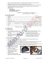
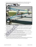
Use masking tape and a length of coat hanger or
heavier wire to guide each servo’s wire from its
servo bay out through the root rib of each wing
panel. (NOTE: If your servo’s leads do not reach
out fully through the root ribs, add a 6-inch servo
extension.)
6.
Use
5/16
-inch (1 cm) wood screws to secure the
aileron servo hatch covers to their wing panels.
7.
Test-fit the ailerons, CA hinges, 2-pronged aileron control horns
and aileron pushrods to the wing panels.
(NOTE: If necessary, use a sharp hobby knife to ream the outer
holes in the aileron control horns to fit the aileron pushrods and cut
through any excess Mylar covering the CA hinge slots and mounting
holes for the aileron’s control horns.)
8.
Center the CA hinges in their slots. Use CA adhesive to attach
permanently the ailerons to their wing panels.
9.
Use masking tape to hold the trailing edges of each aileron aligned
evenly with the trailing edge of its wing panel.
10.
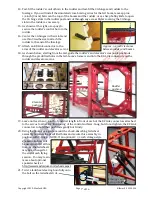
Slide the straight (unbent) end of each aileron pushrod into the
EZ Link connectors on the aileron servo
output arms.
11.
Twist the Z-bend in the aileron pushrods
into the outer holes on the aileron
control horns.
12.
Use CA adhesive to secure the aileron
control horns into the holes in the firm
balsa wood in each aileron.
13.
Securely tighten the EZ Link connectors onto the aileron pushrods.
14.
Leaving at least
1/2
-inch of aileron pushrod length in front of each EZ Link connector
to allow for ‘fine-tuning’ of the ailerons, cut off and discard the ends of the aileron pushrods that
extend excessively forward of their EZ Link connectors.
15.
Remove the masking tape from the ailerons and wing
panels.
16.
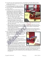
Insert and center both wing rods in the fuselage and
slide the wing panels onto their wing rods.
17.
If you are using the ailerons, position a 6-inch Y harness
inside the fuselage and, as each wing panel nears the
fuselage, connect the aileron servos (or their extensions)
to the open ends of the Y harness.
(NOTE: We recommend using optional servo safety clips to secure all servo-to-
servo extension and/or Y-harness connections.)
18.
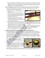
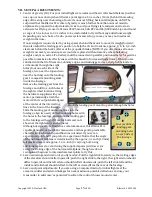
Using pliers, attach four springs to four swivels
and four clips as shown at the right.
19.
Locate the four composite upper
wing-wire-mounting braces and
four approx.
5/16
-inch (1 cm)
screws.
20.
Insert the ends of the upper wing-
wire-mounting braces that have the smaller predrilled holes into the four slotted openings in the
top of the fuselage.
Pull servo lead out
through root rib
Nose
Shown on
1/4
-inch squares
10
of 16


