Copyright 2013: Maxford USA
Page
Blériot XI: S130926
(NOTE: Do not to get any glue inside the horizontal tailplane. In the event of a minor gluing
accident, it may help to use a little acetone on the end of a Q-tip as a solvent.)
7.
Allow the CA adhesive or epoxy to set fully or cure inside the elevator. When the CA adhesive or
epoxy has set or cured, check that the torque rod remains centered within the tailplane.
8.
Being careful not to allow any glue to enter the horizontal tailplane, apply CA adhesive or epoxy
along the outer length of the left-side elevator torque rod. Immediately insert the torque rod fully
into the left-side elevator. Check that the torque rod remains centered within the horizontal
tailplane and able to rotate freely within the horizontal tailplane.
9.
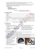
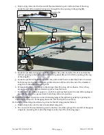
As shown below, before the CA adhesive or epoxy has fully set or cured, place the horizontal
tailplane, torque rod and elevator assembly on a flat surface with their flat lower surfaces facing
down and aligned to each other. Allow the CA adhesive or epoxy to set or cure fully.
10.
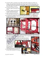
With the horizontal tailplane, torque rod and elevator assembly on a flat surface (with the lower
surfaces facing down as shown above), center the three
elevator control-horn parts on the torque rod and point
the control horn straight
up
.
11.
Firmly press the three wooden elevator control-horn
parts together on the torque rod. Apply thin CA adhesive
to secure the elevator control horn parts to each other
and to the torque rod.
12.
Check that the torque rod is still able to rotate freely
within the horizontal tailplane.
13.
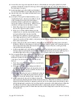
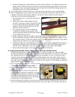
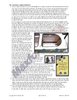
As shown below, attach the horizontal tailplane beneath the tail booms.
Horizontal tailplane
Left
elevator
Right
elevator
Bolts
and nuts shown
on 1/4-inch
squares
Position the elevator horn at
90 degrees to the flat surface
Approx.
3/8
-inch (1 cm) long bolt,
approx. 1
3/16-
inch (3 cm) long bolt, matching self-locking nuts and
approx.
1/2
-inch (13 mm) tall plastic spacer.
NOTE: Do not shorten the approx. 1
3/16-
inch (3 cm) long bolt.
6
of 16


