Page
8
of
13
recommend epoxy for these two
steps because it is less likely to
run and the set up time is more
predictable than CA.
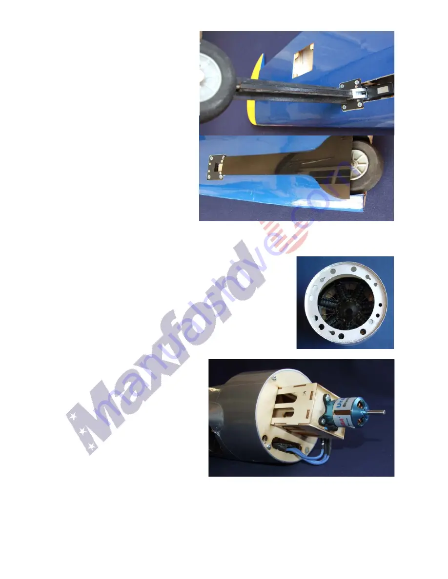
Now extend the gear and glue
the plywood cap over the
exposed metal strut.
Retract the gear again. Locate
the two plastic gear doors and
cut off the bottom half of the
round part. Glue them to the
plywood strut brace.
Locate the fiberglass wing joiner
tube, test fit it into the wings to
make sure the wing tube
sockets are not obstructed.
Slide the tube through the
fuselage and test fit the wing in place.
INSTALL THE MOTOR AND ESC:
The twist-on "Max-Cowling" is a Maxford exclusive.
Notice the three small screws and one magnet near the
edge of the front of the fuselage. Test fit the cowl by
positioning it so that the magnet on the fuselage lines up
with the magnet in the cowl and then pushing the cowl
over the screw heads and twisting the cowl a few
degrees clockwise. If the cowl won't turn, loosen the
screws. If it goes on but is loose, tighten the screws.
Remove the cowl and the sliding
motor mount box. Mount your
motor onto the box, centered on
the X that is scored on the firewall.
Carefully measure back
5 3/8"
from the rear of the propeller and
put a mark on the side of the box.
Slip the box into the fuselage but
DO NOT GLUE IT IN YET.
Install the cowl and verify that the
prop clears the cowl by about 1/2
inch and that the prop shaft is near the center of the opening in the dummy engine.
If you chose to use a different motor and it is longer or shorter than the Maxford
U35425 that we used in the prototypes, you can slide the motor box back or forward
to make prop shaft come out nearer the center of the hole. When you are happy with
the fit go ahead and glue the box into the fuselage.


