Copyright Maxford USA 2017
Page 8 of 12
S171201
To mount your battery and ESCs down inside the fuselage, install three additional wires between your
motors and ESCs using the same process described for installing throttle-servo leads. NOTE: the
benefit of mounting your batteries in the fuselage is that they may be connected in parallel, preventing
any unwanted yaw due to a weak battery. The
nose-compartment’s hatch may be large enough to
allow battery and ESC installation in the nose and
to recharge your batteries between flights.
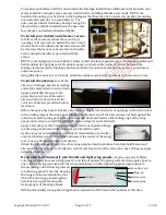
To install your rudder and elevator servos
,
test-fit and if necessary adjust the servo tray’s
openings to fit your servos, harden the servo tray’s
wood with thin CA adhesive where the screws will
be inserted, then mount your elevator and rudder
servos using the hardware provided with the
servos.
NOTE: some flying-boat owners like to reinforce their airplanes against long-term vibration, water and
hard landings by applying extra 30-minute epoxy to all accessible points of contact between the
fuselage formers and the fuselage’s bottom and sides; if you choose this option, now is a good time to
add some epoxy.
Using EZ-Link connectors or Z-bends, attach the rudder and elevator pushrods to their servos’ arms.
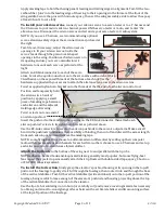
To install the ailerons
, test-fit the
ailerons, CA hinges, and the projecting
ends of the metal aileron control rods.
Apply a small dab of epoxy to the
projecting end of one of the metal
aileron control rods and insert the
control rod into the predrilled hole in
its aileron.
Before the epoxy has time to thicken, insert the CA hinges into their precut openings in the aileron and
in the trailing edge of the wing panel. (Make sure the inner end of the aileron does not bind against the
cutout in its mating wing panel; also, leave enough clearance between the trailing edge of the wing
panel and its aileron so full UP and DOWN aileron travel is not restricted.)
Apply a few drops of thin CA to permanently secure each aileron hinge
into its wing panel and into its aileron as pictured at the right.
As the epoxy cures, hold the aileron control rod and aileron so the free
end of each aileron control rod (the end nearest the center of the wing)
is at or near a 90-degree angle to its aileron.
Attach the remaining aileron to the other wing panel as described above. Carefully hold this second
aileron while epoxy cures so its aileron control rod’s free end is at the same at or near 90-degree angle
as the first aileron.
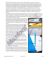
If you wish to permanently join the left and right wing panels
, cut away any excess Mylar
covering material from each wing panel’s root rib to maximize the gluing surfaces, then apply epoxy to
one end of the wing rod and insert the wing rod midway into the right wing panel. Apply epoxy to
the projecting end of the wing rod and
to both wing panel’s root ribs. Keeping
the wing rod centered, slide the root
ribs of the two wing panels together.
Carefully line up the leading and
trailing edges of the wing panels.
NOTE: permanently joining the wing panels is optional. Do NOT attach the tip floats at this time.
Carbon-fiber ‘pin’
Wing rod
Aileron servo
Oval opening
Tip float


