Page 1 of 10
ARF U-control Profile
S141208
P R O F I L E P - 4 7 & P - 5 1
ARF U-CONTROL
GLOW-ENGINE OR EP-POWERED AIRPLANE
I N S T R U C T I O N M A N U A L
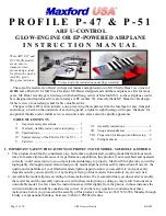
These ARF P-47 and
P-51 Profile models
are an easy-to-
transport, time-
proven design, ideal
for pilots who want a
versatile, great
flying sport airplane.
These profile models are offered with special thanks and appreciation to Mr. Charlie Bauer. As owner of
4
π
RC
and a District VI AMA Vice President, Mr. Bauer designed and sold these airplanes as kits for many
years. Mr. Bauer recently gave his design to Richard Sang, owner of Maxford USA, so these airplanes could
be redesigned and reproduced for sale in today’s ARF market. We sincerely thank Mr. Bauer for his design,
for his review of our redesign, and for his valuable advice.
Changes in the ARF version include: a one-piece wing that separates from the fuselage for easy transport
and storage; a hatch on the underside of each wing panel; a lighter weight fuselage with open ‘channels’ for
an optional throttle and/or rudder servo’s extension; and a more scale-like profile appearance.
TABLE OF CONTENTS
I. Important safety precautions .............................. 1
II. Warranty, liability waiver, and return policy ..... 2
III. Specifications ..................................................... 3
IV. Special features of the P
ROFILE
P-47 & P-51 ..... 3
V. Parts list ............................................................. 3
VI. Assembly instructions ................................ 4
VII. Setup and adjustments ............................... 9
VIII. Preparation for transport and field setup ... 9
IX. Preflight checks ......................................... 9
I. IMPORTANT SAFETY PRECAUTIONS TO PROTECT YOUR MODEL, YOURSELF & OTHERS:
1.
This product should not be considered a toy, but rather a sophisticated, working model that functions much
like a full-scale airplane. Because of its performance capabilities, this product, if not assembled and operated
correctly, could cause injury to you or spectators and damage to property. Maxford USA provides you with a
high-quality, thoroughly tested almost-ready-to-fly model airplane with assembly instructions. However, the
quality and capabilities of your finished model airplane depend on how you assemble it, and your safety
depends on how you use and fly it. Any testing or flying of this model is done entirely at your own risk.
2.
Assemble the model airplane according to these instructions. We recommend that you do not alter or modify
the model beyond the assembly options covered in these instructions, as doing so may result in an unsafe or
unworkable model. In a few cases the instructions may differ slightly from the photos; in those instances the
written instructions should be considered as correct. If you have any question or concern about these
instructions, before you proceed with assembly of this product, contact us at (562) 529-3988, Monday through
Friday, except national holidays, between 9 AM to 5 PM Pacific time.
Pictured with the included optional flaps installed.


