Page 5 of 10
ARF U-control Profile
S141208
8.
Remove the tape from the rudder and vertical stabilizer.
9.
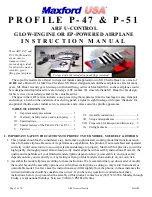
Bend the tail-wheel’s strut 90 degrees toward the rear (over the tail wheel) and cut off and discard all but
1/2
-
inch of the bent end of the tail-wheel’s strut. Insert the bent end of the tail-wheel’s strut into the hole in the
rudder and secure the strut to the rudder with epoxy.
10.
When the epoxy has cured fully, test-fit CA hinges into the precut slots in the rudder, vertical stabilizer and
the back edge of the fuselage. Use CA adhesive to secure each hinge.
11.
Use wood screws to secure the tail-wheel assembly to the bottom of the fuselage. (Reinforce the holes in the
bottom of the fuselage with thin CA adhesive.)
12.
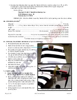
Test-fit the rudder’s control horn on the left side of the rudder and the elevator’s control horn on the bottom-
right side of the elevator. Center the adjustment holes in each horn on its hinge line. Drill holes and attach the
rudder and elevator control horns with the supplied bolts and back plates.
13.
Fit the rudder pushrod’s Z-bend into the rudder’s control horn and point the length of the pushrod toward the
nose.
14.
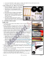
Test-fit a control horn against the solid wood between the 2 openings on the left side of the fuselage at
approx. 2 1/2 inches forward of the rudder’s control horn. Mark where the control horn needs to be mounted
onto the side of the fuselage.
15.
Mount an EZ-Link connector to a control horn and mount the control horn to the side of the fuselage.
16.
Attach the rudder pushrod between the rudder’s control horn and the EZ-Link connector on the control horn
mounted on the side of the fuselage.
17.
Set the angle of the rudder by adjusting the rudder’s pushrod in its EZ-Link connector. Tighten the EZ-Link
connector onto the rudder’s pushrod to secure the rudder.
WING –
1.
Remove the wing’s center section
from the fuselage.
2.
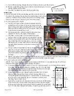
Test-fit the wing panels to the
wing’s center section by guiding
the two plywood wing spars into either wing panel, through the center section,
and fully into the second wing panel. (NOTE: The included bellcrank is pre-
installed at the root rib inside the
RIGHT
wing panel’s equipment bay; be sure to
position the equipment bay-hatch covers on the
BOTTOM
of the wing.)
3.
Align each wing panel’s root rib with the center section.
4.
Use epoxy to permanently secure the wing panels to the spar and center section.
5.
If you will install the included optional flaps:
a)
If necessary, cut through any Mylar covering the precut CA-hinge slots for
the flaps. Test-fit the flaps’ CA hinges into their slots in the flaps and the
wing panels.
b)
Test-fit a wire flap coupler (not included) to the wing and mark where to cut
or drill an opening for the flap coupler in the wing’s center section and to
drill openings in the flaps for your flap coupler.
Twin plywood spars
Bellcrank


